OnAir 2500 Digital Mixing Console
Quick Reference Guide 17
Document generated: 09.09.14
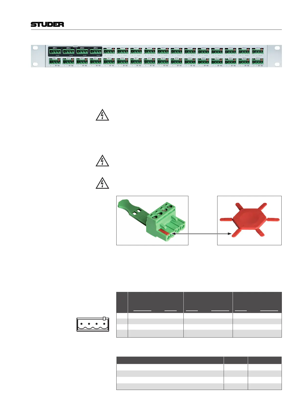
For easier wiring of single GPI and/or GPO signals, this break-out box can
be used. 16 GPI signals and 12 of the 16 GPO signals of a GPIO card with
relayoutputs(A949.0436)arewiredtosingle,4-pin‘Combicon’terminals
(seebelow),providingtherelaycontactsoropto-couplerinputs,aswellas
GNDandashortcircuit-proof5VDCsupply.
If voltages exceeding 50 V (AC or DC) are switched, the break-out box must
be placed within a closed rack in order to avoid shock hazards by touching
the contacts.
Fourofthe16GPOsignals(GPO1...4,marked in black on the front panel)
are connected to solid-state relays whose power terminals are wired to the
‘Combicon’ terminals.ThesepowercontactscanswitchACloadsfrom
24...240 V with a maximum total current of 5 A over all 4 relays.
For safety reasons, these four terminals have no additional GND and 5 V
supply. All remaining low-voltage terminals (GPI 1...16, GPO 5...16) are
coded on pin #4 in order to prevent high-voltage connectors being inserted
by mistake.
The high-voltage connectors must be coded, as shown below; six coding
elements (order no. C054.251100) are included with the break-out box.
Coding Element
Eight4-pin‘Combicon’plugswithscrewterminals(C054.251104)are
includedwiththebreak-outbox. If more plugs arerequired, please order
separately.Ontherearoftheboxtwo37-pinD-typesockets(f)areprovided
for connection to the GPIO card. For matching cables please refer to the table
below.
Pin Assignment
Pin
GPO 1...4 (Outputs)
(upper row, Sockets
UNcoded/Plugs coded)
GPO 5...16 (Outputs)
(upper row, *Sockets
coded/Plugs UNcoded)
GPI 1...16 (Inputs)
(lower row, *Sockets
coded/Plugs UNcoded)
*
1 n.c. +5 V +5 V
2 n.c. GND GND
3 Solid-State Relay, Contact 1 GPO Relay, Contact 1 Optocoupler Input 1
4 Solid-State Relay, Contact 2 GPO Relay, Contact 2 Optocoupler Input 2
Cables for Break-Out Boxes
Description Length [m] Order no.
DB25 m-m 1:1 cable, 8 × shielded 0.45 C089.201161
DB25 m-m 1:1 cable, 8 × shielded 0.9 C089.201174
DB25 m-m 1:1 cable, 8 × shielded 1.5 C089.201170
DB37 m-m 1:1 cable 0.9 C089.201178
 Loading...


