OnAir 2500 Digital Mixing Console
12 Quick Reference Guide
Document generated: 09.09.14
8 Power-up
The power switch is located next to the 100-240V~ [10] mains inlet.
If using an external DC power supply unit connected to 24V DC IN [9], the
console can be switched on and off with the PSU’s power switch.
For battery operation an external switch must be connected in series with the
supply cable. Please note that for battery operation, an external, UL approved
fuse (T 5 A H 250 V UL/CSA) must be connected in series with one of the
supply lines as well.
After switching on, the console performs a self-test routine, starts the operat-
ing software and loads the initial snapshot.
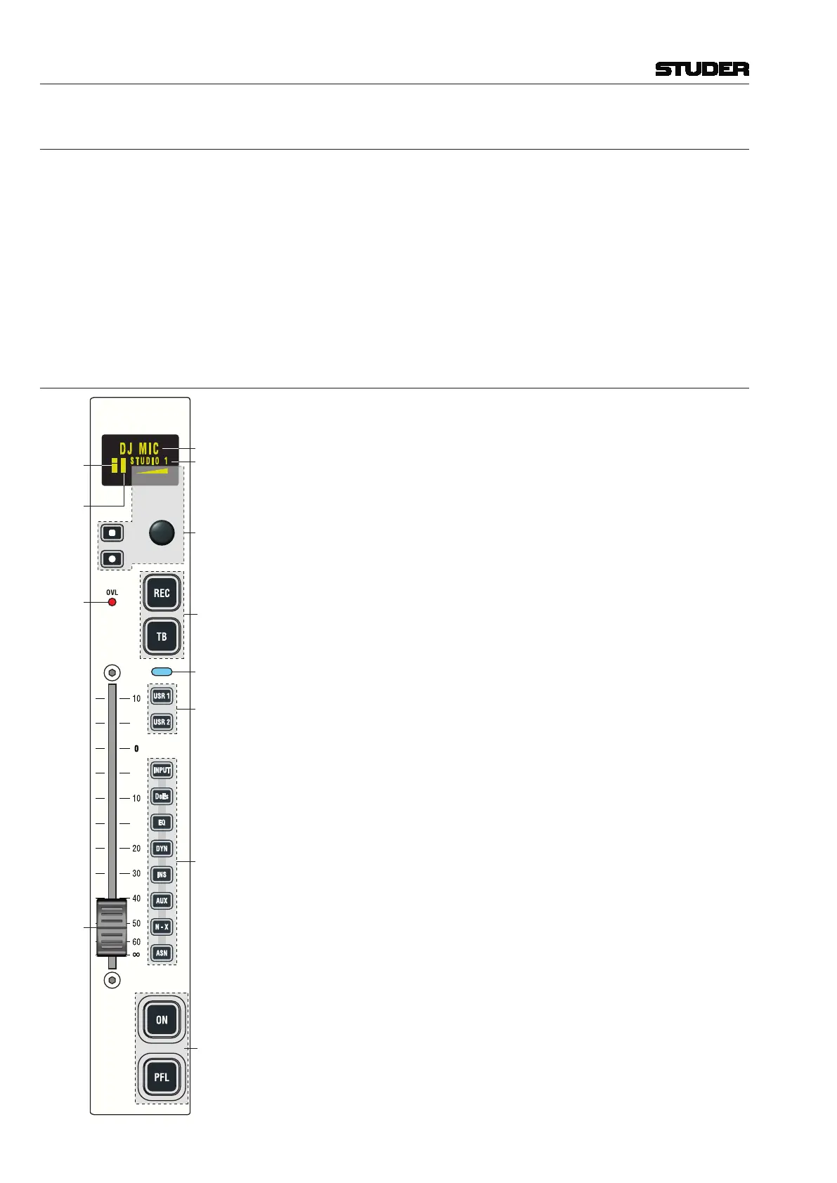
9 The Fader Strip
Channel
Label
T
Channel
Rotary
Encoder
Pro-
gramm-
able
Keys
Pro-
gramm-
able
Keys
Channel
Active
User
Keys
Direct
Access
Keys
Level
Meter
Gain
Red.
Meter
(GRM)
Overload
Indicator
Fader
100 mm
(Motor &
Over-
press
Optional)
EveryfaderstripincludesagraphicalOLEDscreenthatcontainsthechannel
label, level and gain reduction meters and parameter readout, selected with the
rotary assign section in the central module. The 100 mm faders can optionally
bemotorized.
A rotary encoder combined with two keys below the display is used to set
channel parameters.
Themainchannelfunctionsareaccessedwithfourlarge,illuminatedkeys:
• REC (record),usedtoassignthechannelsignaldirectlytotherecordbus,
regardless of the fader position, the ON key, and the bus assignment. If
active, the key is illuminated in red.
• TB(talkback).ForN–Xownerchannels,thiskey’sfunctionisTB(talk-
back)totheN–Xreturn.Ifmorethanoneownerisconfiguredtothesame
N–Xoutput,allcorrespondingTB keys work in parallel.
• ON(channelon/off)Pressingthekeytogglesthechannelon/offfunction.
In the audio path, the on/off switch is located after fader and panning.
On status is indicated by illuminating the key.
The function is disabled when the corresponding fader is configured as
master fader for a particular bus.
• PFL(pre-faderlistening)
The purpose of PFL is to feed the pre-fader audio signal of the desired
channelorAUXsend,group,ormaster(program,record)tothePFLbus.
If active, the key is illuminated in yellow.
Twouserkeyscanbeusedforcustomizedfunctionality.
Eight small direct access keys activate the corresponding channel functions
in the main screen for comfortable editing.
More information on operation and configuration: See OnAir 3000 oper-
ating instructions.

 Loading...


