11
DISASSEMBLY/ASSEMBLY PROCEDURES
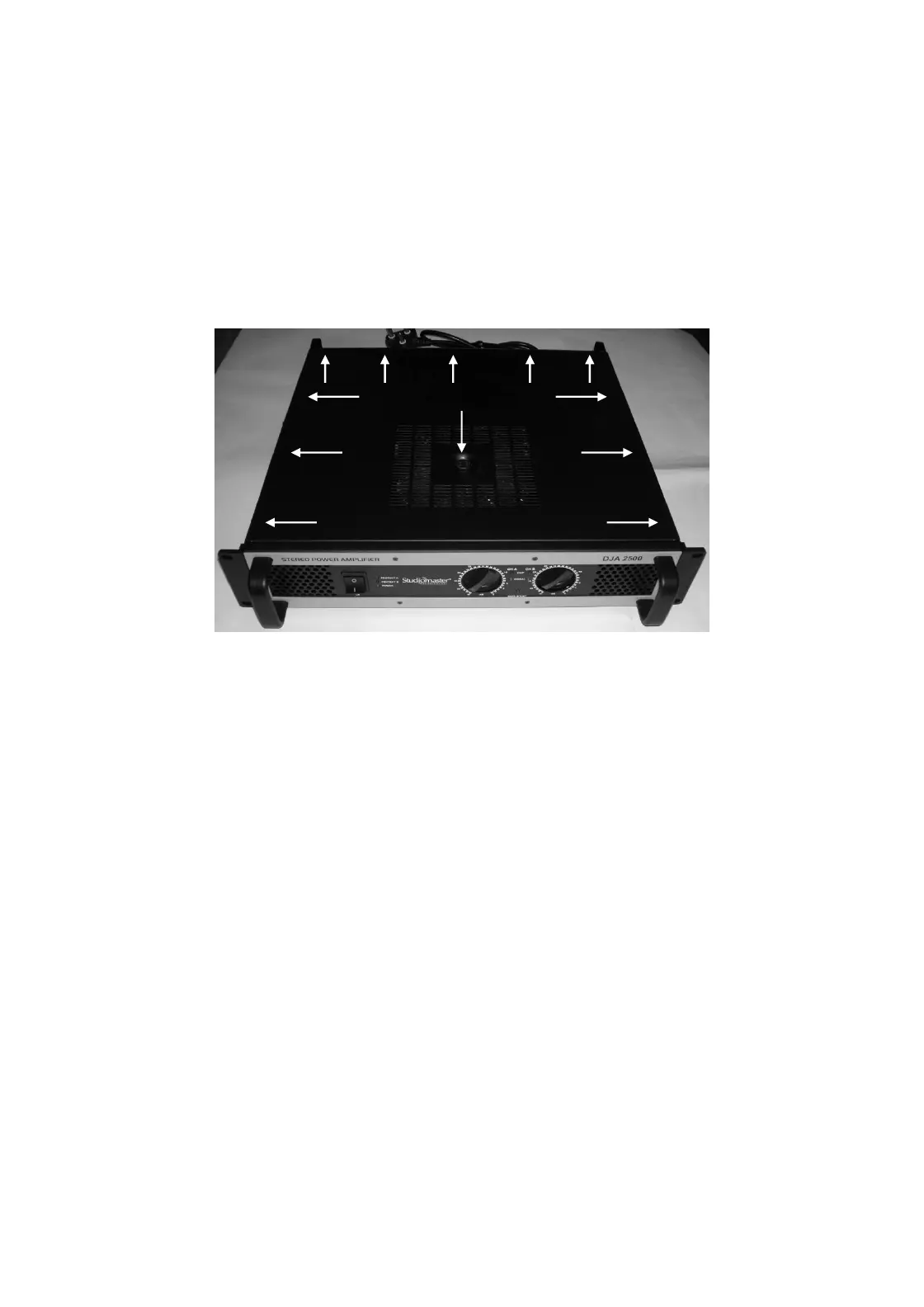
1. Top Cover Removal
1.1 Remove transformer mounting hex Bolt
1.2 Remove side left, right (3 each) & rear (5 nos.) M4X5, Allen Head screws (11 nos.)
2.0 Top Cover Replacement.
2.1 Place the top cover and fit side and rear screws mentioned in 1.2
2.2 Fit the transformer mounting hex bolt.
3. Power Amplifier PCB Removal
3.1 Perform procedure 1.
3.2 Disconnect the wire looms going to power amp pcb.
3.3 Remove bottom heatsink fitting screws M4X10 Self Tap Black.
(DJA2500 – 3 nos/heatsink, DJA4000 – 5 nos./heatsink)
3.4 Lift the board upward carefully.
4. Power Amplifier PCB Replacement
4.1 Re-connect the wire harness as mentioned in 3.2.
4.2 Place the module in to the chassis.
4.3 Align the mounting holes and refit it by screws mentioned in 3.3
Transformer