18
DC VOLTAGES
All DC voltages are with reference to GND
D) DC1, DC5: +15.5V
E) DC2, DC4: HV= +/-143V, LV=+/-70V
F) DC3: +/- 11.7V
- Switch off the mains supply.
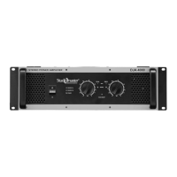
B. AMPLIFIER UNIT TEST PROCEDURE DJA2500
1. Select the Amplifier in pre setting using switch on the Back plate.
- Amplifier in Stereo Mode.
- CROSSOVER/LOWCUT switch in OFF position.
- EQ Processing in OFF position
2. Keep Variac at minimum position.
3. Connect amplifier mains plug to Variac socket.
4. Turn on the unit & increase mains supply slowly and check that there is no loading (rapid increase in
primary current).
5. If there is no loading, adjust supply voltage to 240VAC.
- Observe that when power is switched ON, POWER ON LED will turn on.
- After a short delay of 5 sec. the amplifier turns on.
- The PROTECT and TEMP LED’S, will switch on with power on condition and then will switch off
with some delay.
6. DC OFFSET VOLTAGE
Check the DC voltage at the Output points. The DC offset voltage should be within ± 10 mV.
7. BIAS ADJUSTMENT
On the driver transistor 2SC4793 & 2SA1837 (either one accessible in the unit) w. r. t ground there
should be 1.3V (±0.2V) measured. If not adjust preset on the power amp PCB to get 1.3V (±0.2V)
8. AMP PERFORMANCE MEASUREMENT:
1) SENSITIVITY
- Drive single channel into 4 ohms load in Stereo mode at 1 kHz.
- Increase the input to get 66V (1100 W) just clipped output.
- The input required to get 66V output is the rated sensitivity.
- The Specification for the Sensitivity is 1.3V (±0.3V)
Input connectors check:
XLR balanced: Use XLR balance male connector (pin 2 “+”, pin 3 “-“& pin 1-gnd) from generator to
XLR socket and check sensitivity as above.
Stereo jack – Use stereo jack connector (Tip “+”, Ring “-“and Shield –GND) from generator to JACK
socket and check sensitivity as above.
2) FREQUENCY RESPONSE MEASUREMENT:
- Drive single channel into 4 ohms load in Stereo mode at 1 kHz.
- Apply input of the rated sensitivity and adjust the output to 30V using gain control pot.
- Change the frequency of the applied input and note the output reading.
FREQUENCY
20Hz 1KHz 20K
OUTPUT/ CH 28-32V 30V 28-32V
3) POWER V/S THD
I. Stereo Mode Single Channel Driven.
- Single channels driven in various load conditions.
- Gain pot MAX.
- Feed 1KHz signal & adjust output at just clipping level.
Power Output in V
Ch 1 Ch 2
Load