16
/07.2016/G20
Gerät 51 71 91 131 151
Druckleitung mm 12 12 12 16 16
Flüssigkeitsleitung mm 10 10 10 10 10
Gerät 51 71 91 131 151
Druckleitung
Px 419 419 419 414 401
Py 224 214 252 266 263
Pz 247 247 247 248 236
Flüssigkeitsleitung
Lx 520 520 520 514 514
Ly 214 214 214 215 215
Lz 224 224 224 222 222
Ly
Py
Px
Pz
Lx
Lz
32 126 46 144 46 146 32
x
z
y
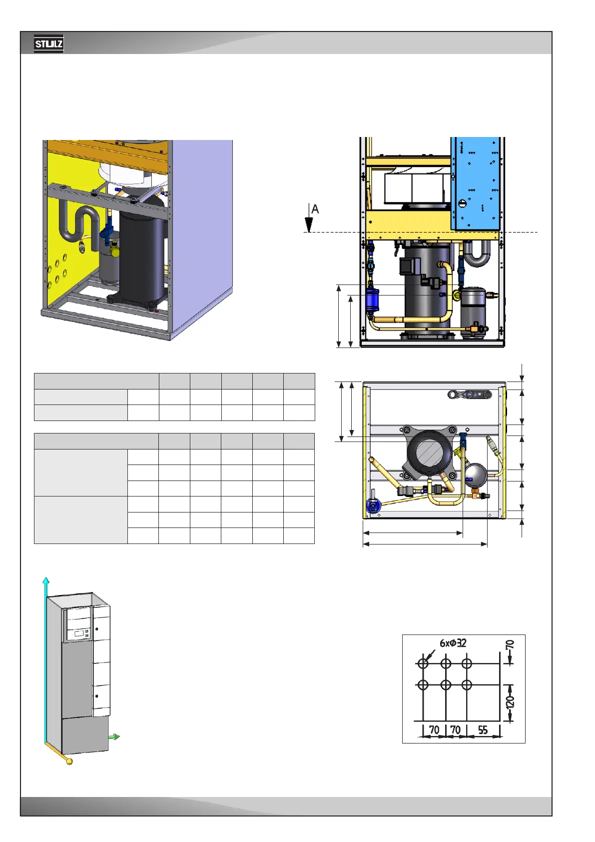
Downflow - CCD 51/71/91/131/151 A
EN
6.3.1.2 Position of the refrigerant connections
Refrigerant line connection
The refrigerant connections are located near the compressor and are la-
belled by the inscriptions "pressure pipe" and "liquid pipe". The lines to be
connected have to be soldered.
Section A-A
Rear view:
Front view:
In general the pipes of downflow
units are routed through the raised
floor out of the unit. However you can
route them through openings in the
right side panel. See the position and
dimension of the openings in the right
drawing. The point of reference is the
right, rear corner below.
All dimensions in mm.
Unit
Pressure line mm
Liquid line mm
Unit
Pressure line
Px
Py
Pz
Liquid line
Lx
Ly
Lz