/07.2016/G20
17
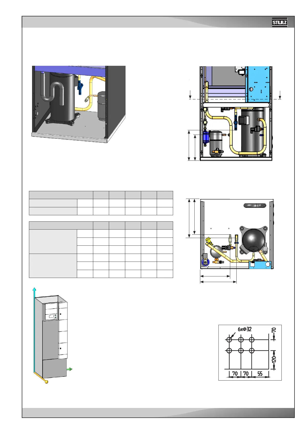
Gerät 51 71 91 131 151
Druckleitung mm 12 12 12 16 16
Flüssigkeitsleitung mm 10 10 10 10 10
Gerät 51 71 91 131 151
Druckleitung
Px 296 296 296 293 297
Py 198 208 235 255 281
Pz 304 304 304 321 325
Flüssigkeitsleitung
Lx 244 244 244 241 245
Ly 214 214 214 215 215
Lz 288 288 288 288 288
Px
Pz
Lx
Lz
x
z
y
Ly
Py
A
A
Upflow - CCU 51/71/91/131/151 A
EN
Refrigerant line connection
The refrigerant connections are located near the compressor and are la-
belled by the inscriptions "pressure pipe" and "liquid pipe". The lines to be
connected have to be soldered.
Section A-A
Rear view:
Front view:
The pipes of upflow units are routed
through openings in the right side
panel. See the position and dimension
of the openings in the right drawing.
The point of reference is the right, rear
corner below.
All dimensions in mm.
Unit
Pressure line mm
Liquid line mm
Unit
Pressure line
Px
Py
Pz
Liquid line
Lx
Ly
Lz