18
/07.2016/G20
Gerät 181 221 251
Druckleitung mm 16 16 16
Flüssigkeitsleitung mm 16 16 16
Gerät 181 / 221 251
Druckleitung
Px 561 566
Py 115 110
Pz 222 288
Flüssigkeitsleitung
Lx 766 771
Ly 88 87
Lz 278 286
Ly
Py
Px
Pz
Lx
Lz
52 187 50 148 50 251 52
x
z
y
55 70 70
120 70
2 x 50
4 x 32
AA
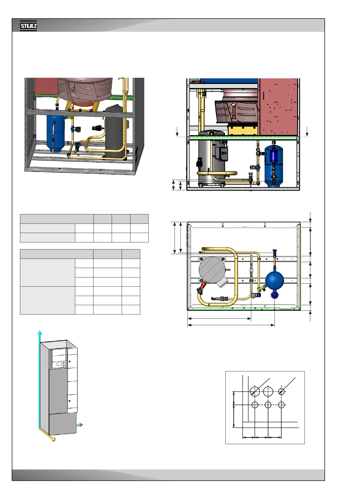
Downflow - CCD 181/221/251 A
EN
Refrigerant line connection
The refrigerant connections are located near the compressor and are la-
belled by the inscriptions "pressure pipe" and "liquid pipe". The lines to be
connected have to be soldered.
Section A-A
Rear view:
Front view:
In general the pipes of downflow units
are routed through the raised floor out
of the unit. However you can route
them through openings in the left side
panel. See the position and dimension
of the openings in the right drawing.
The point of reference is the left, rear
corner below.
All dimensions in mm.
Unit
Pressure line mm
Liquid line mm
Unit
Pressure line
Px
Py
Pz
Liquid line
Lx
Ly
Lz