/07.2016/G20
19
Gerät 181 221 251
Druckleitung mm 16 16 16
Flüssigkeitsleitung mm 16 16 16
Gerät 181 / 221 251
Druckleitung
Px 560 560
Py 119 119
Pz 235 282
Flüssigkeitsleitung
Lx 765 765
Ly 96 96
Lz 279 279
Ly
Py
Px
Pz
Lx
Lz
x
z
y
55 70 70
120 70
2 x 50
4 x 32
A A
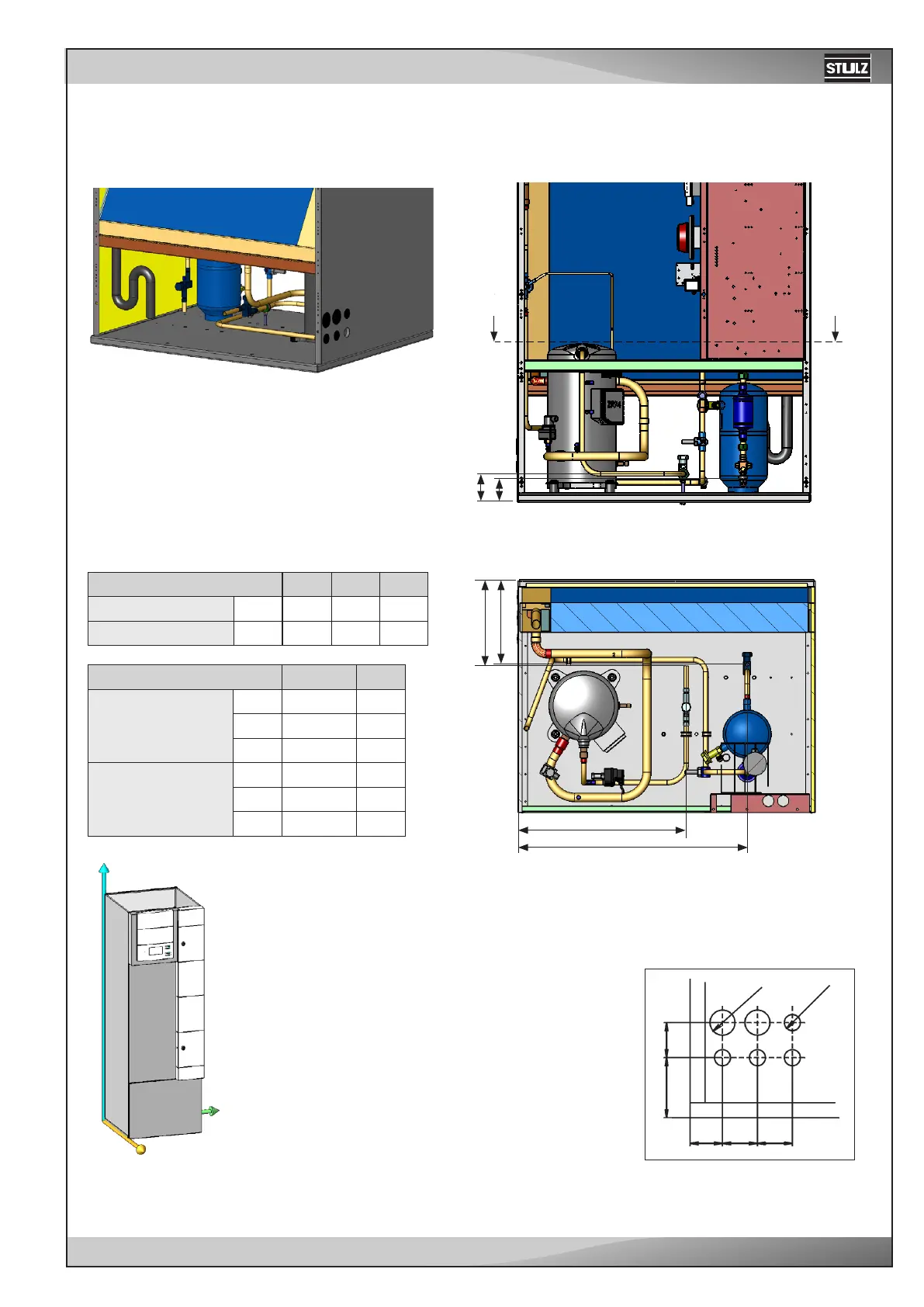
Upflow - CCU 181/221/251 A
EN
Refrigerant line connection
The refrigerant connections are located near the compressor and are la-
belled by the inscriptions "pressure pipe" and "liquid pipe". The lines to be
connected have to be soldered.
Section A-A
Rear view:
Front view:
The pipes of upflow units are routed
through openings in the left side pa-
nel. See the position and dimension
of the openings in the right drawing.
The point of reference is the left, rear
corner below.
All dimensions in mm.
Unit
Pressure line mm
Liquid line mm
Unit
Pressure line
Px
Py
Pz
Liquid line
Lx
Ly
Lz