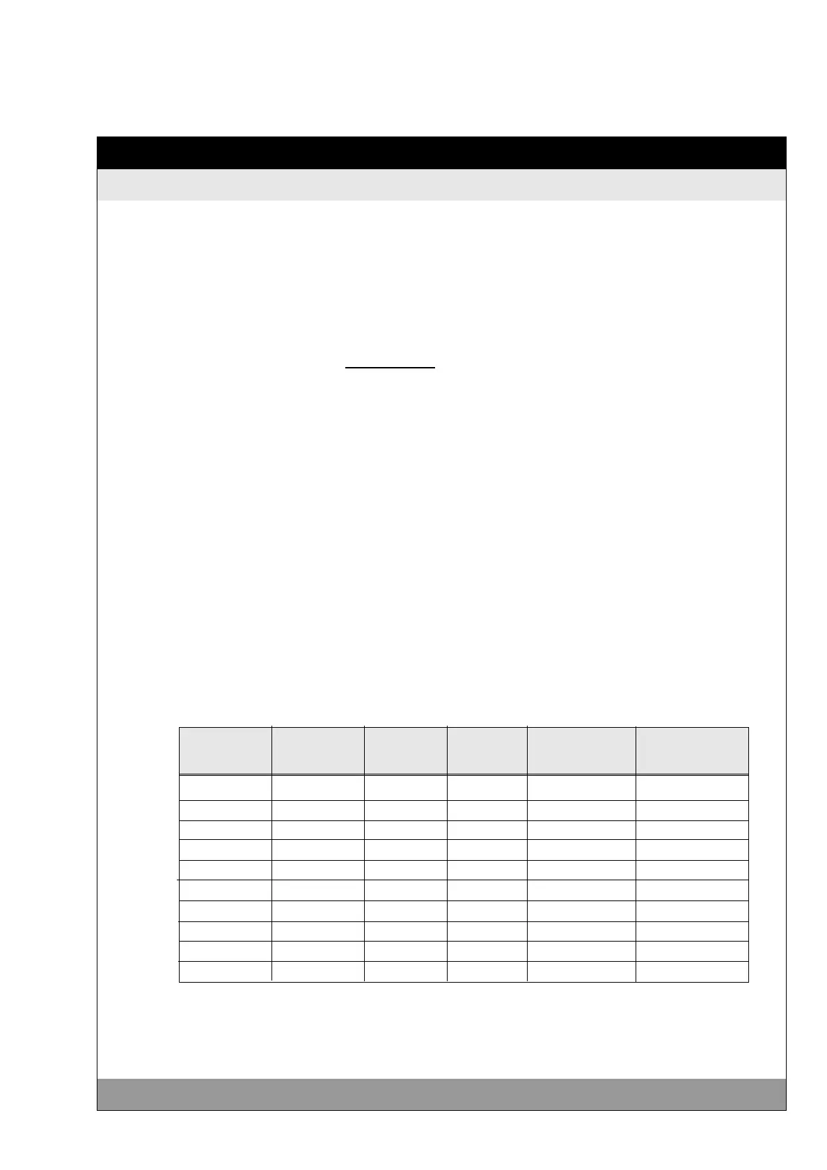
ULTRASONIC
35
Copyright STULZ GmbH 02/1997
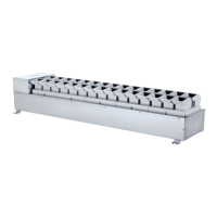
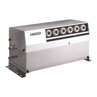
Connecting Lines between Humidifiers and Control System
4. Cable Dimensioning
The connecting cable between the humidifier and the control vox (trans-
former) reduces the voltage at the humidifier and corresponds to the
following formula:
i
L
I
A
If the voltage loss between the control bos and the humidifier is smaller
or equal 4%, the voltage is still within the tolerance range. If the value
falls below this voltage, a larger cable cross section in accordance with
the table has to be chosen or the voltage has to be connected at
transformers secondary side to 52 VAC.
ENS 1200 1 48 VAC 1,35 A 60 m 100 m
ENS 2400 1 48 VAC 2,60 A 31 m 51 m
ENS 3600 1 48 VAC 3,85 A 21 m 35 m
ENS 4800 1 48 VAC 5,00 A 16 m 27 m
ENS 6000 1 48 VAC 6,46 A 13 m 21 m
ENS 7200 1 48 VAC 7,81 A 10 m 17 m
ENS 8400 1 48 VAC 9,06 A 9 m 15 m
ENS 9600 1 48 VAC 10,31 A 8 m 13 m
ENS 14 2 48 VAC 2x 7,81 A 10 m 17 m
ENS 18 2 48 VAC 2x 10,0 A 8 m 13 m
The two oscillator rows of ENS 14 and ENS 18 are fed via two separate
leads, the current is therefore separated and therefore the maximum
cable length is increased in the standard cross section.
Type Oscillator Voltage Current max. cable max. cable
rows intensity length 1.5 mm² length 2,5 mm²
i =
1000 x A
35,6 x L x I
= Voltage loss [V]
= Cable length [m]
= Current intensity [A]
= Cable cross section [mm²]