Electronic Control System
3-19
#7019014 - Revision A - October, 2010
Built-In (BI) Series
Built-In (BI) Series
FUNCTIONS OF THE ELECTRONIC CONTROL SYSTEM
The following pages explain monitoring, regulating and controlling functions of the electronic control system. In most
cases signal traces on a model BI36U wiring schematic are used to show current flow for functions being explained.
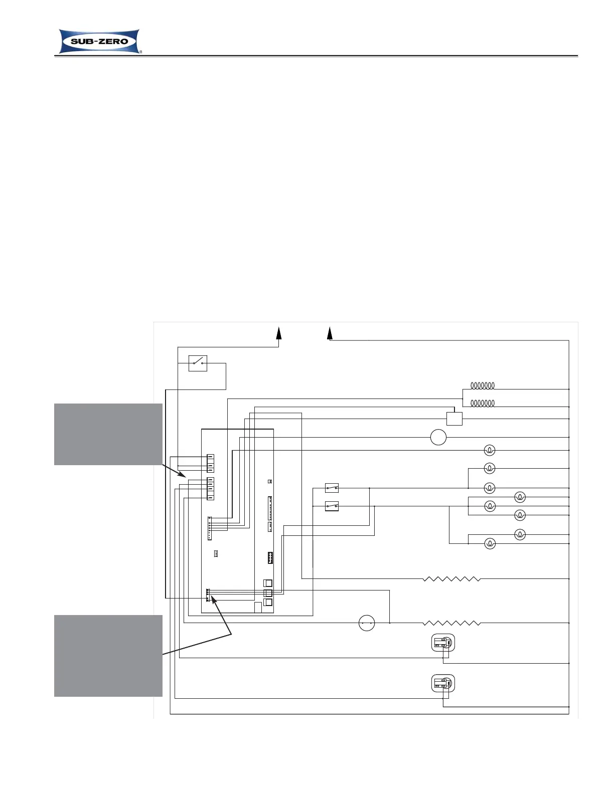
Supply Power to the Lighting System
Power is supplied to the lighting system through the control board when the unit is switched ON by pressing the
POWER key. When a door is open, the corresponding normally closed light switch allows power to the lights in the
compartment (See Figure 3-37).
NOTES:
• Power to the light is monitored by the microprocessor to control the door ajar alarm feature.
• Power to the refrigerator lights is also monitored to help control the refrigerator evaporator fan and air purifier fan
operation. When the refrigerator door is open, power to the evaporator fan is interrupted.
• Power to the freezer lights is also monitored to help control the freezer evaporator fan and icemaker operation. If
the freezer door (or drawer) is open, power to the freezer evaporator fan and the icemaker is interrupted.
• If in Sabbath Mode, the lighting system is disabled.
Figure 3-37. Signal Trace Schematic: Lighting System
 Loading...