Electronic Control System
3-3
#7019014 - Revision A - October, 2010
Built-In (BI) Series
Built-In (BI) Series
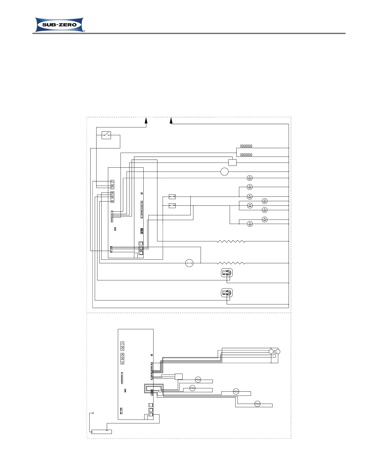
Figure 3-1. Electronic Control System Overview (BI-36UG Wiring Schematic)
ELECTRONIC CONTROL SYSTEM OVERVIEW
Figure 3-1 is the wiring schematic for the model BI-36UG showing the components of the electronic control system.
• Manual input operations are performed at the Control Panel Assembly (Keypad).
• Monitoring, regulating and controlling functions take place at the Main Control Board.
• Temperatures, icons and function/diagnostic codes are displayed in the LCD (part of Keypad).
The entire electronic control system is described in greater detail on the following pages.
NOTE: For more detailed electrical diagrams refer to the wiring diagram and schematic supplied with the appliance.