EasyManua.ls Logo

Sub-Zero Built-in Series - Page 24

Sub-Zero Built-in Series
45 pages
To Next Page IconTo Next Page
To Previous Page IconTo Previous Page
Loading...
Electronic Control System
3-25
#7019014 - Revision A - October, 2010
Built-In (BI) Series
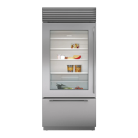
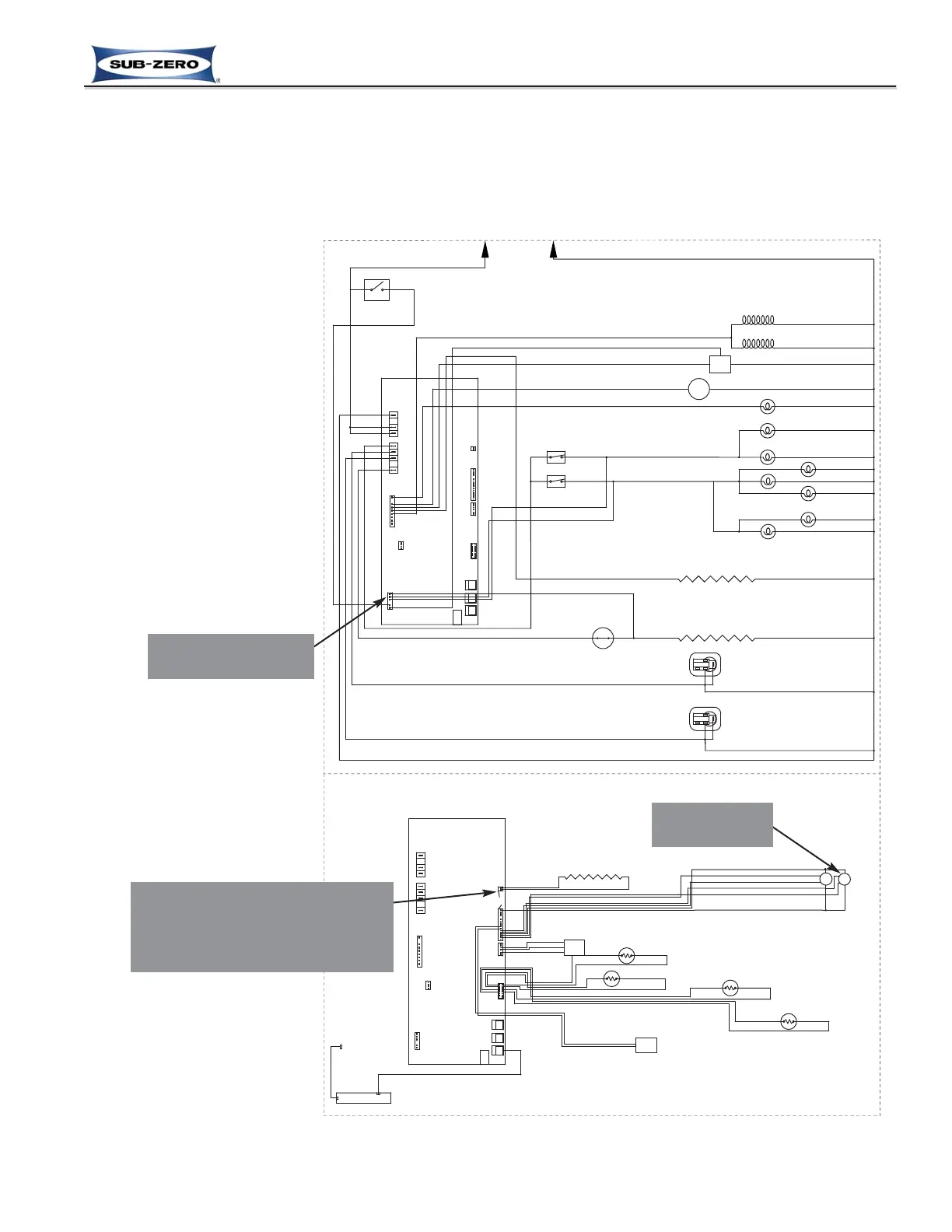
Minimize Condensation on Refrigerator Door Glass (Models Produced with Glass Doors Only)
On models with glass refrigerator doors a low DC voltage, five (5) watt braided wire heater is foamed into the door
around the glass perimeter. This heater helps to minimize the formation of condensation on the glass and/or door
frame by energizing in ten (10) to forty (40) second ON/OFF cycles, depending on the compartment temperatures;
colder temperatures equal longer cycles. (See Figure 3-43).
To help minimize condensation
further, the microprocessor
detects when the refrigerator
door is opened, via the light
switch, and when the door clos-
es the evaporator fan is ener-
gized for five (5) minutes,
regardless of the refrigerator
compressor operational state,
drawing any warmer moist air
away from the door glass.
(See Figure 3-43)
115 VOLTS
60 CYCLES
L1
NEUTRAL
N.O.
WATER FILTER SWITCH
P16
MAIN
CONTROL
BOARD
P1
3
P14
L1
L1
NEUTRAL
1164
P2
P15
85
P3
P6
P5
P6
P9
P8
P7
P18
DEFROST HTR
COMP2
COMP1
MAIN LIGHTS
N.C.
N.C.
FZ DOOR SWITCH
REF DOOR SWITCH
ISOLATION VALVE
660 Ω
WATER VALVE
160 Ω
M
IM
CONDENSER FAN MOTOR
CRISPER LIGHTS
REF LIGHTS
AIR FILTER LIGHT
FREEZER LIGHTS
FILL-TUBE HEATER
2300-2900 Ω
DEF HEATER
27.9-30.9 Ω
DEFROST TERMINATOR
REFRIGERATOR COMPRESSOR
STARTING RELAY
FREEZER COMPRESSOR
STARTING RELAY
PURPLE
WHITE
WHITE/BLUE
WHITE/BLUE
BLUE
WHITE
PURPLE
GRAY
RED
PINK
YELLOW
BLACK
RED
WHITE/BLUE
TAN
BLUE
ORANGE
YELLOW
YELLOW
ORANGE/BLACK
GRAY/WHITE
ORANGE/BLACK
WHITE
RED/WHITE
WHITE/RED
TAN
PINK
GRAY
ORANGE
WHITE
WHITE
WHITE
WHITE
WHITE
WHITE
WHITE
WHITE
WHITE
WHITE
WHITE
WHITE
WHITE
WHITE
TAN/WHITE
TAN/WHITE
BROWN
YELLOW
WHITE
REF
EVAPORATOR FAN
FREEZER
EVAPORATOR FAN
M
M
FLOW
METER
THERMISTER FREEZER EVAP
THERMISTER FREEZER CABINET
THERMISTER REF CABINET
THERMISTER REF EVAP
BROWN
BLACK/WHITE
WHITE/BLACK
BLUE
BROWN
BLUE
BROWN
YELLOW
RED
YELLOW/BROWN
BLUE/WHITE
BROWN
BLUE
BLUE
BROWN
BLUE
WHITE
MAIN CONTROL
BOARD
16
1
17
1
P18
3
P6
P15
P16
85
P14
1164
P6
P9
P8 P7
P5
P2
P3
P1
DEFROST HTR
COMP2
COMP1
MAIN LIGHTS
L1
NEUTRAL
L1
EXERNAL
DEVICE
KEYPAD
LOW VOLTAGE
HIGH VOLTAGE
LED
GLASS DOOR HEATER
24.9 Ω - 31.7 Ω
WHITE/PURPLE
BLUE/PURPLE
WHITE/PURPLE
BLUE/PURPLE
BLACK/YELLOW
WHITE/YELLOW
Figure 3-43. Signal Trace Schematic: Glass Door Unit Door Heater &
Evaporator Fan Operation
3. Evaporator
fan energized
1. Power supplied to door heater in
10 - 40 second ON/OFF cycles at
all times. Cycle length depends on
compartment temperature. Colder
temperatures = longer time on.
2. Signal that ref. door
opened and closed
Previous Page
Main Menu
Built-In Series Menu
Previous Page
Main Menu
Table of Contents
Next Page
Next Page

Other manuals for Sub-Zero Built-in Series

Related product manuals