Suburban DynaPack A&E Manual 07/2019 Rev.6
21
S SERIES
CONDENSATE DRAIN
The DynaPack unit and wall sleeve each have their own drain. The unit drain is
for the condensate developed by the evaporator coil. It needs to be trapped and
routed to the building drain system. Use 3/4" pvc pipe and fittings (field
supplied).
The wall sleeve is equipped with a drain pan that collects rain water entering
the wall sleeve and the unit condenser coil area. At the time of installation of
the wall sleeve, this drain can be directed directly outside or turned inside and
routed to the building drain system. If the wall sleeve drain is routed to the
building sewer system then it must be trapped to prevent sewer gasses
from escaping.
DUCT WORK
The duct work for the dwelling should be designed for the lowest possible
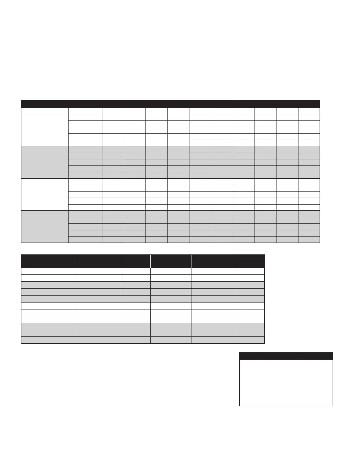
static pressure to reduce energy usage and noise. Table 4 lists the approximate
cfm delivery of the units on each of the indoor blower speeds. Table 5 lists the
recommended heating and cooling speeds with its approximate cfm delivery.
Use both tables to properly design the duct system for both heating and
cooling cfm.
(continued on next page)
S SERIES INDOOR CFM vs STATIC PRESSURE (Dry coil + no air filter)
MODEL NUMBER
Blower Speed 0.10" wc 0.15" wc 0.20" wc 0.25" wc 0.30" wc 0.40" wc 0.50" wc 0.60" wc 0.70" wc 0.80" wc
DYPA12AC3A
LO
497 473 448 424 400 348 296 247 212 160
MED LO
577
562 547 522 497 458 415 357 317 281
MED 757
748 739 716 692 670 635 586 558 521
MED HI 937
920 905 888 872 852 827 790 728 677
HI 1060
1050 1042 1015 977 927 876 824 758 700
DYPA18AC3A
LO
512 491 469 428 387 320 285 250 213 179
MED LO
596
568 540 522 504 447 415 381 324 291
MED 773
761 748 730 711 675 640 622 586 550
MED HI 972
955 938 927 915 874 850 825 796 766
HI 1108
1091 1074 1057 1039 1002 970 917 868 796
DYPA24AC3A
LO
504 483 461 420 379 312 252 207 N/R N/R
MED LO
588 560 532 514 496 439 377 320 262 202
MED 765
753 740 722 703 667 622 572 532 482
MED HI 964
947 930 919 907 866 828 782 757 702
HI 1100
1083 1066 1049 1031 994 962 922 882 827
DYPA30AC3A
LO
490 465 440 415 385 310 225 170 N/R N/R
MED LO
570
540 520 500 476 415 365 310 250 205
MED 768
755 741 732 704 666 621 580 535 500
MED HI 934
922 913 895 873 835 800 760 730 690
HI 1064
1046 1017 1009 995 965 935 900 875 828
TABLE 4
MODEL NUMBER
Recommended
Heating Speed
Approx.
CFM
Approx.
Temp Rise ºF
Recommended
Cooling Speed
Approx.
CFM
DYPA12AC3A036
MEDIUM 700 38 LOW 400
DYPA12AC3A048
MEDIUM 700 50 LOW 400
DYPA18AC3A036
MEDIUM 700 38 MEDIUM LOW 550
DYPA18AC3A048
MEDIUM 700 50 MEDIUM LOW 550
DYPA18AC3A060
MEDIUM HIGH 900 50 MEDIUM LOW 550
DYPA24AC3A036
MEDIUM 700 38 MEDIUM 700
DYPA24AC3A048
MEDIUM HIGH 900 40 MEDIUM 700
DYPA24AC3A060
MEDIUM HIGH 900 50 MEDIUM 700
DYPA30AC3A036
MEDIUM 700 38 MEDIUM HIGH 900
DYPA30AC3A048
MEDIUM HIGH 900 40 MEDIUM HIGH 900
DYPA30AC3A060
MEDIUM HIGH 900 50 MEDIUM HIGH 900
TABLE 5
NOTE
Follow local codes and standards
when designing duct runs to deliver
the required airflow. Minimize noise
and excessive pressure drops caused
by duct aspect ratio changes,
bends, dampers and outlet grilles in
duct runs.
 Loading...