Suburban DynaPack A&E Manual 07/2019 Rev.6
12
VENTING/VENT PIPE INSTALLATION
(continued on next page)
VENTING
The DynaPack unit uses outside air for combustion and vents the exhaust
products directly outside. The DynaPack unit cannot be vented with other
appliances. The venting system of the DynaPack unit cannot be modified
or adjusted in any manner other than what is specified in these instructions.
The installation must be planned before hand so that the unit exhaust vent
location complies with local or national codes in regards to distances between
the unit vent and doors, operable windows, side walks, balconies, and patios.
See the National Fuel Gas Code Z223.1 for the USA or Installation Code
CANI-B149 for Canada. See Figure 2.
The DynaPack unit venting system is certified to operate at wind speeds up to
40 miles per hour.
The DynaPack unit contains an adjustable vent. The vent must be adjusted
based on the wall sleeve used for proper operation.
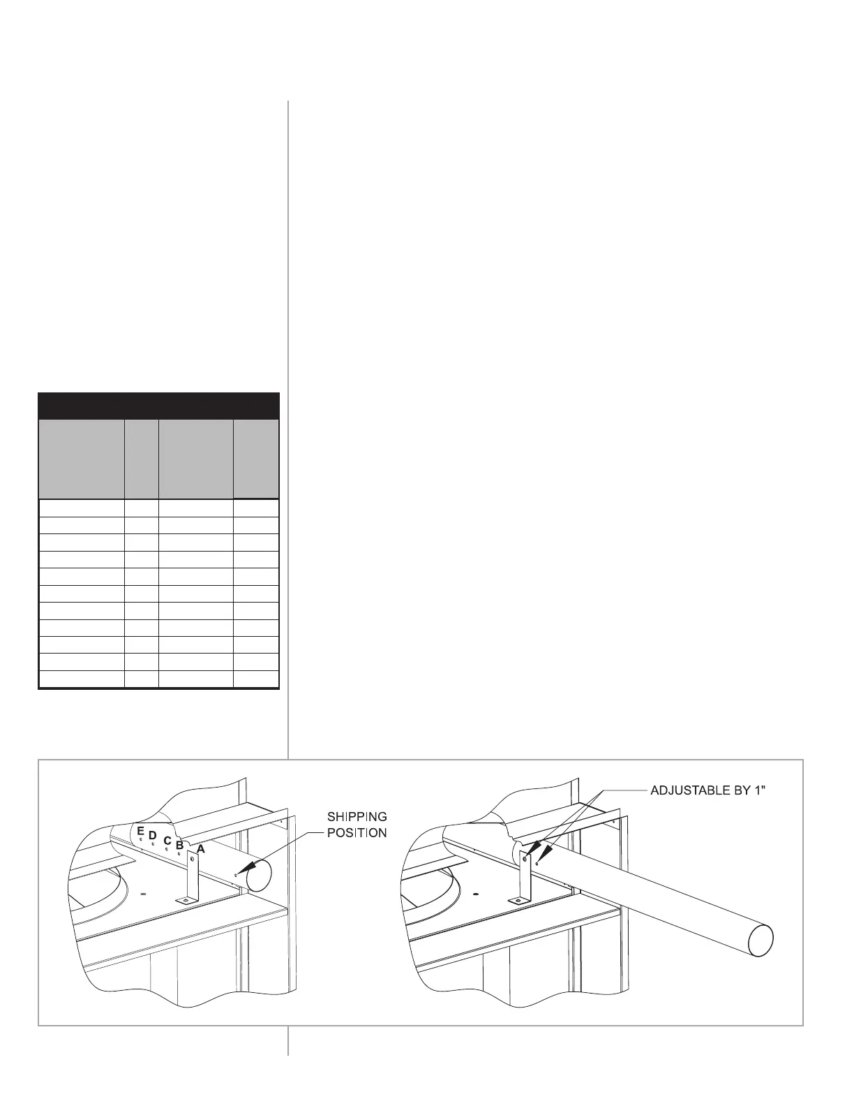
VENT PIPE ADJUSTMENT FOR S SERIES UNITS
The vent pipe must be adjusted to match the depth of the wall sleeve.
CAUTION: Failure to properly adjust the vent can lead to exhaust
recirculation and poor combustion.
1. The vent pipe adjustment is accessible from the condenser air
discharge portion of the unit. The retaining screw for the vent pipe
is located to the right of the condenser fan.
2. Remove and retain the #10 sheet metal screw which attaches the
vent pipe to its mounting bracket. See Figure 3.
3. The vent extension tube contains six holes, each of which is
intended for a particular wall sleeve depth. Use Figure 3 to select the
proper mounting hole for the vent extension tube.
4. Reinstall the #10 sheet metal screw to secure the vent extension tube
and exhaust tube to its mounting bracket.
FIGURE 3 - S SERIES
* Each exhaust tube is specific to
each sleeve depth.
TABLE 1
Wall Sleeve
Stock
Number
Hole #
Approximate
Length the Vent
Extends from
the Cabinet
Nominal
Wall
Sleeve
Depth
DETERMINING HOLE SETTING
1736 or 1741
A
4-3/8" 4"
1737 or 1742
B
6-3/8" 6"
1738 or 1743
C
8-3/8" 8"
1739 or 1744
D
10-3/8" 10"
1740 or 1745
E
12-3/8" 12"
1769 or 1770
*
14-3/8" 14"
1771 or 1772
*
16-3/8" 16"
1773 or 1774
*
17-3/8" 17"
1821 or 1822
*
18-3/8" 18"
1823 or 1824
*
20-3/8" 20"
1825 or 1826
*
22-3/8" 22"
 Loading...