6-18
#7013455 - Revision A - April, 2009
Component Access/Removal
International W
International W
ine Storage
ine Storage
(ICBWS)
(ICBWS)
Series
Series
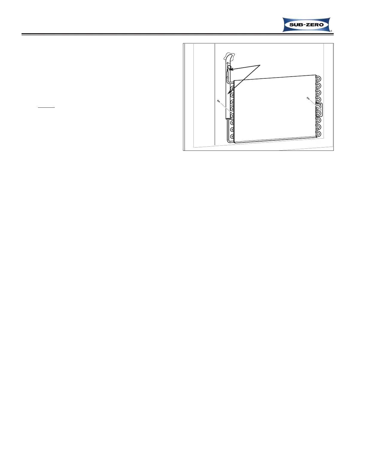
Evaporator
The evaporators are attached to the rear wall of the
compartments with screws, behind the compartment
duct assemblies. See Duct Assembly removal proce-
dures earlier in this section.
NOTE: Whenever servicing the sealed system, the
refrigerant valve assembly (which includes the filter-
drier) MUST
be replaced.
To remove the evaporator, first capture the refrigerant
from the sealed system, then (See Figure 6-37):
1. Extract evaporator mounting screws, then pull and
rotate evaporator so heat exchanger is accessible.
2. With a file, score a line around capillary tube, 1” or
less from evaporator inlet, then fatigue capillary
tube at this line until it separates.
3. With a tube-cutter, cut suction tube 1” or less from
evaporator outlet stub, then remove evaporator
from compartment.
NOTES:
• Do not sweat tubing apart. Doing so will induce
moisture into the sealed system.
• After capillary tube separates, check tubing for inter-
nal burrs. If burrs exist, repeat step 2 above.
Figure 6-37. Evaporator Removal
(Lower Evaporator Shown)
Evaporator
Cut Here