6-17
#7013455 - Revision A - April, 2009
Component Access/Removal
International W
International W
ine Storage
ine Storage
(ICBWS)
(ICBWS)
Series
Series
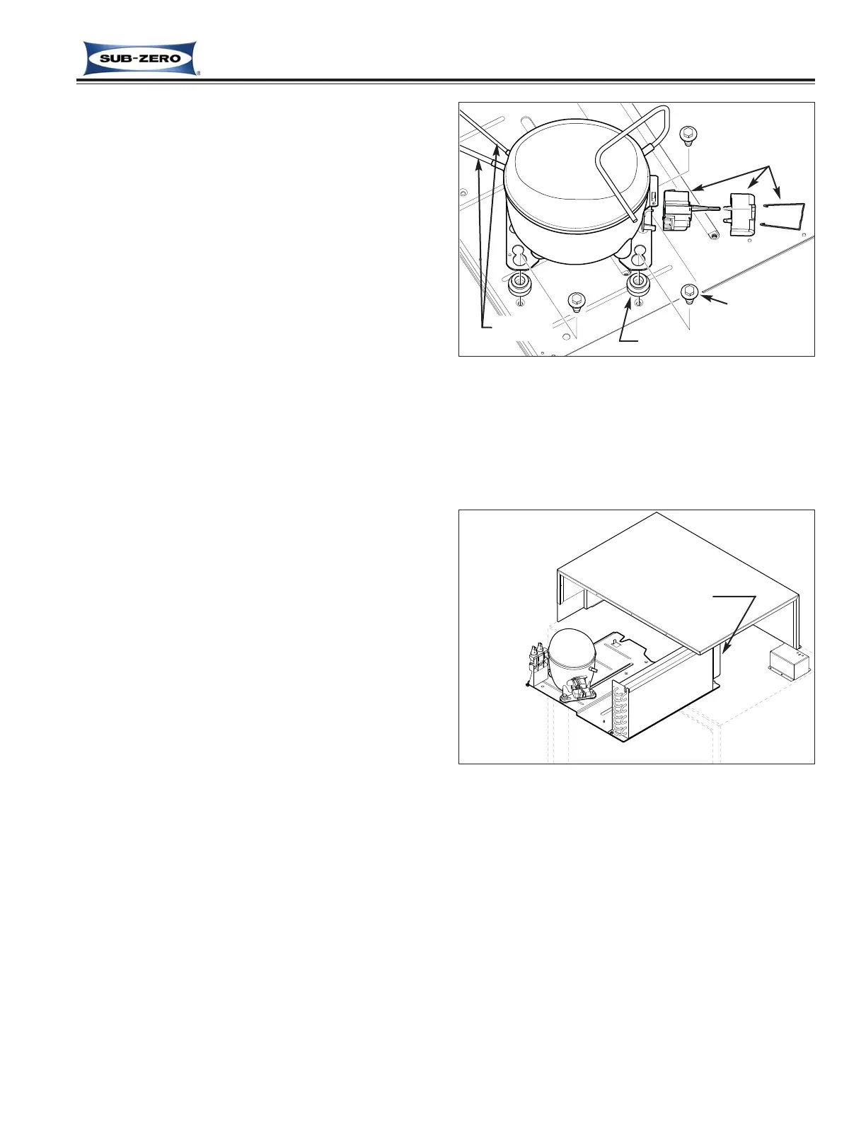
Compressor
The Compressor is secured to the unit tray with three
shoulder screws that pass down through rubber grom-
mets in the compressor base and into holes in unit tray.
A metal tab formed into the unit tray passes up through
the fourth rubber grommet and the compressor base.
NOTE: See information, WARNING and NOTES under
the heading of Model ICBWS-30 Sealed System
Components before continuing.
After capturing the refrigerant from the sealed system,
(See Figure 6-35):
1. Disconnect wire leads from compressor electricals.
2. Using a tube cutter, cut suction and discharge tubes
approximately 1” from compressor stubs.
NOTE: Do not sweat tubing apart. Doing so will
induce moisture into the sealed system.
3. Extract compressor mounting shoulder screws, then
lift compressor off of unit tray.
NOTE: After replacing the compressor, take care to not
kink tubing as the unit tray is slid back into position.
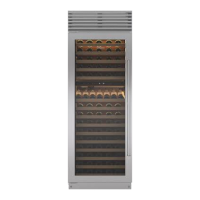
Condenser
Holes in the front and rear bottom flanges of the con-
denser fit over threaded studs in the unit tray, then a
nut is applied to each threaded stud to hold the con-
denser in place.
NOTES:
• See information, WARNING and NOTES under the
heading of Model ICBWS-30 Sealed System
Components before continuing.
• The condenser inlet and outlet stubs are at the rear
of the condenser.
After capturing the refrigerant from the sealed system,
(See Figure 6-36):
1. Remove nuts from threaded studs at the front and
rear of condenser, then lift condenser slightly to
clear threaded studs and pull condenser forward.
2. Using a tube cutter, cut condenser inlet and outlet
tubes approximately 1” from condenser stubs, then
remove condenser fully from unit tray.
NOTES:
• Do not sweat tubing apart. Doing so will induce
moisture into the sealed system.
• After replacing the condenser, take care to not kink
tubing as the unit tray is slid back into position.
Figure 6-35. Compressor Removal
Cut Here
Compressor
Shoulder
Screws (3)
Rubber Grommets (4)
Compressor
Electrical
Assembly,
Capacitor & Clip
Figure 6-36. Condenser Removal
Inlet and Outlet
are at back of
Condenser
Condenser