EasyManua.ls Logo

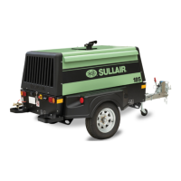
Sullair 185 CFM User Manual

Sullair 185 CFM
132 pages
To Next Page IconTo Next Page
Page #1 background imageLoading...
Page #1 background image
PORTABLE AIR
COMPRESSOR
125, 130, 160H, 185 CFM
and 49 HP Models
CATERPILLAR, JOHN DEERE, PERKINS
OPERATOR’S
MANUAL AND
PARTS LIST
KEEP FOR
FUTURE
REFERENCE
Part Number
02250159-733
©Sullair Corporation
The information in this document
is correct at the time of printing
for Portable Compressor Serial
Number :
004-151422
and all subsequent Serial
Numbers.

Table of Contents

Questions and Answers:

Sullair 185 CFM Specifications

General IconGeneral
Model185 CFM
Air Flow185 CFM
Weight2, 240 lbs (Dry)
Dimensions123.4" L x 61.5" W x 57.4" H
Power SourceDiesel

Summary

Section 1 SAFETY

1.1 GENERAL

General safety precautions for operating the air compressor.

1.2 TOWING

Instructions and precautions for safely towing the compressor.

1.4 FIRE AND EXPLOSION

Safety measures to prevent fire and explosion hazards.

1.8 ELECTRICAL SHOCK

Warnings and precautions to avoid electrical shock.

1.11 JUMP STARTING

Step-by-step guide for safely jump-starting the compressor.

Section 2 DESCRIPTION

Section 3 SPECIFICATIONS

3.1A SPECIFICATIONS - PERKINS AND CATERPILLAR

Technical specifications for Perkins and Caterpillar engine models.

3.1B SPECIFICATIONS - JOHN DEERE 125, 130 (2-WHEEL AND LRG)

Technical specs for John Deere 125/130 (2-wheel/LRG).

3.1C SPECIFICATIONS - JOHN DEERE 49HP, 160H, 185 (2-WHEEL AND LRG)

Technical specs for John Deere 49HP/160H/185 models.

Section 4 OPERATION

4.3 START-UP PROCEDURE

Detailed steps for the initial compressor start-up.

4.5 SHUTDOWN PROCEDURE

Steps for properly shutting down the compressor.

Section 5 MAINTENANCE

5.11 PARTS REPLACEMENT AND ADJUSTMENT PROCEDURES

Detailed procedures for replacing parts and making adjustments.

5.13 TROUBLESHOOTING GUIDE

Chart listing symptoms, causes, and remedies for common problems.

Section 6 NOISE CONTROL

6.2 TAMPERING WITH THE NOISE CONTROL SYSTEM IS PROHIBITED

Legal prohibition against tampering with noise control systems.

Section 7 ILLUSTRATIONS AND PARTS LIST

7.2 RECOMMENDED SPARE PARTS LIST

List of recommended spare parts for the compressor.

7.3A ENGINE, COMPRESSOR AND PARTS - PERKINS AND CATERPILLAR MODELS 125, 130 & 185

Illustrated parts breakdown for engine and compressor.

7.3B ENGINE, COMPRESSOR AND PARTS - JOHN DEERE MODELS 125, 130, 185 & 49HP

Illustrated parts breakdown for John Deere engine/compressor.

7.3C ENGINE, COMPRESSOR AND PARTS - JOHN DEERE MODEL 160H

Illustrated parts breakdown for John Deere 160H engine/compressor.

7.4A AIR INLET AND EXHAUST - PERKINS AND CATERPILLAR MODELS 125, 130 & 185

Illustrated parts for air inlet and exhaust systems.

7.4B AIR INLET AND EXHAUST - JOHN DEERE MODELS 125, 130, 185, 49HP & 160H

Illustrated parts for John Deere air inlet/exhaust systems.

7.5 RADIATOR AND COMPRESSOR FLUID COOLING SYSTEM - ALL MODELS

Illustrated parts for the cooling system.

7.6 FRAME, RUNNING GEAR AND PARTS - ALL MODELS

Illustrated parts for the frame and running gear.

7.7A DISCHARGE SYSTEM AND PARTS - ALL MODELS EXCEPT JOHN DEERE 160H

Illustrated parts for the discharge system (non-160H JD).

7.7B DISCHARGE SYSTEM AND PARTS - JOHN DEERE MODEL 160H

Illustrated parts for the discharge system (160H JD).

Related product manuals