Section 2
185 T3 Kubota User Manual 2: Description
02250223-054 R01
Subject to EAR, ECCN EAR99 and related export control restrictions. 15
Description
2.1 Introduction
The Sullair 185 T3 Kubota standard portable air com-
pressor offers superior performance, reliability and
requir
e a minimal amount of maintenance. Compared to
other compressors, Sullair’s are unique in terms of reli-
ability and durability. Compress
or internal components
re
quire no routine maintenance inspections.
2.2 Description of components
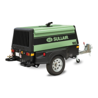
Figure 2-1 on page 16 shows the main components and
subassemblies of the Sullair 185 T3 Kubota standard
port
able air compressor. These packages include a
heavy duty rotary screw air compressor, a diesel engine,
fuel tank, compressor inlet system, compressor cooling
and lubrication system, compressor discharge system,
capacity control system, instrument panel and electrical
system. A low profile canopy offers improved handling
and mobility. A clamshell canopy provides easy access to
all serviceable components.
The control system can easily be adjusted for pressures
from 80
to 100 psig
(5.6 to 6.9 bar). The compressor unit
is driven by a
n industrial diesel engine designed to pro-
vide enough horsepower to provide an adequate reserve
under rated cond
itions.
Refer to the Engine O
perator’s Manual for a more
detailed description of the engine. The engine cooling
system is comprised of a radiator, high capacity fan, and
thermostat. The high capacity fan pushes air through the
radiator to maintain the engine’s specified operating tem-
perature. The same fan also cools the fluid in the com-
pressor cooling and lubrication system.
The engine radiator and the compressor fluid cooler are
ne
xt to ea
ch other allowing the fan air to push through
both simultaneously. As air passes through the fluid
cooler, the heat of compression is removed from the fluid.
2.3 Sullair compressor air end,
functional description
Sullair compressors are single-stage, positive displace-
ment, oil-flooded lubricated-type compressors that pro-
vide continuous (pulse-free) compression
to meet
various demand loads. Sullair compressors require no
routine maintenance or inspection of their internal parts
or systems. The compressor works by injecting fluid into
the compressor unit where it mixes directly with the air as
the rotors turn. The fluid flow has three main functions:
• It acts as a coolant, to control the rise of air
temp
erature which is
generated by compres-
sion (heat of compression).
• Seals the leakage paths between the rotors
and the stator and also between the rotors
themselves.
• Lubricates the rotors allowing one rotor to
directly drive the other.
After the air/fluid mixture is discharged from the compres-
sor air end, the fluid is separated from the air. At this
time, th
e air flows
to the service line and the fluid is
cooled in preparation for re-injection.
2.4 Compressor cooling & lubrication
system, functional description
Refer to Figure 2-2 on page 17. The compressor cooling
and lubrication system is designed to provide adequate
lubrication as
well as maintain the proper operating tem-
perature of the compressor. In addition to the fluid cooler
and interconn
ecting piping, the system consists also of
three other components: a fluid filter, thermal valve, and a
fan which perform the following functions:
• The fluid filter removes and collects any con-
tami
nants in the fluid.
• The thermal valve functions as a temperature
regulator directing fluid either to the cooler or to
the compressor unit.
• The fan pushes air through the cooler dissipat-
ing the heat resulting from compression of the
fluid.
The functions of the lubrication
system are explained in
more det
ail below. Fluid is used in the system as a cool-
ant and as a lubricant: the sump serves as the fluid reser-
voir. At start-up, fluid flows from the sump to the fluid
 Loading...