SECTION 2 4500P-7500 USER MANUAL
17
fluid filter port. There is also a sight glass that
enables the user to check the receiver tank fluid
level. See Section 4.5.
2.5 CONTROL SYSTEM -
FUNCTIONAL DESCRIPTION
Refer to Figure 2-5. The compressor control
system regulates its output to match the demand.
This system consists of a solenoid valve, a
regulator and an inlet valve that control the
compressor’s four operational modes. The following
descriptions of operational modes apply to a
compressor whose operating range is 100 to 110
psig (6.9 to 7.6 bar)
START MODE - 0 TO 50 PSIG (0 TO 3.5 BAR)
There is no load on the compressor at startup, the
solenoid valve is open and the inlet valve is closed.
When the compressor (START) pad is pressed,
the receiver tank pressure rises from 0 to 50 psig (0 -
3.4 bar). When it reaches its full operating speed
(maximum rpm), the compressor switches to the Full
Load Mode.
Other pressure settings can be selected depending
on compressor application or rating.
I
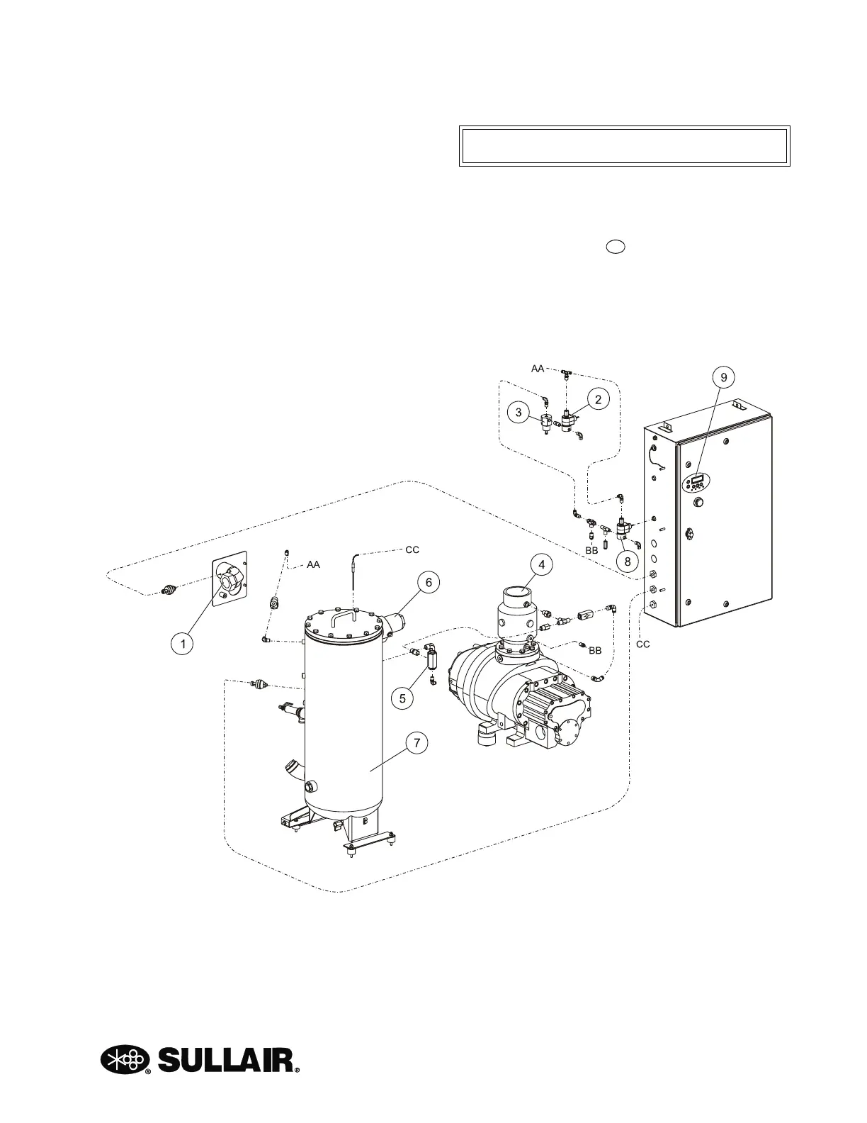
Figure 2-5: Standard Sequencing Control System
1. Air Outlet
2. Sequencing Solenoid Valve
3. Pressure Regulator
4. Air Inlet
5. Blowdown Valve
6. Minimum Pressure / Check Valve
7. Receiver Tank
8. Unload Solenoid Valve
9. WS Controller
 Loading...


