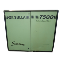
4500P-7500 USER MANUAL SECTION 4
50
WATER-COOLED COMPRESSORS
• Water-cooled compressors require a cool-
ing water supply delivered at a constant
rate and volume. (See Table 4-1 Water
Flow Requirements. The table data applies
to full load operation using an aftercooler.)
• Compressor input and return lines must be
one inch in diameter minimum, and have
isolation valves with side drains. The input
water line should have a 2mm strainer
installed in-line. A solenoid valve (normally
closed), controlled by the compressor con-
trol circuit, should be connected to the
compressor’s water outlet. (Contact Sullair
Customer Care for assistance.)
• Cooling water quality is a critical factor
effecting proper machine cooling. Exces-
sive deposit build-ups, such as lime or
scale, restrict the water flow and act as
thermal insulators. These deposits can
increase the compressor’s operating tem-
perature by reducing the cooling system’s
efficiency.
• Regularly inspect and clean all water piping
and coolers.
• Table 4-2 Ventilation Requirements speci-
fies the minimum ventilation required for
compressor operation at normal tempera-
tures. The fan air requirement applies to
the volume of air that must pass though the
compressor to ensure proper ventilation.
The heat rejection requirement applies the
amount of heat generated by the compres-
sor which must be removed to maintain a
normal operating temperature.
• If the compressor has a water regulating
valve, it can be used to adjust the compres-
sor temperature to maintain a minimum of
185°F (82.2°C); 195°F (87.8°C) for 24 KT
machines.
• Temperature and pressure gauges should
be installed for water system troubleshoot-
ing.
WATER SYSTEM VENTING
Vent the system after installation, or after draining
the system at startup:
1. Open the water valve(s).
2. Open the vent cocks (located on top of the
aftercooler and lubricant cooler) and let air
escape from the system. Close the vent
cocks when water is visible at their location -
at this point the system has been vented.
DRAINING THE WATER SYSTEM
To drain the system completely:
1. Disconnect both the inlets and discharge
water lines located at the rear of the com-
pressor.
NOTE
The required flow rate depends upon the cooling
water’s temperature before it enters the cooling
system. The higher the initial temperature, the
higher the required flow rate: the lower the initial
temperature, the lower the required flow rate.
NOTE
The “waste heat” from air-cooled compressors
can be used for local space heating. If it is used
for this purpose, the additional static pressure
drop across the fan should not exceed 0.2 in.
H
2
0. The high static fan option is required if
ductwork is added. Contact Sullair Custom Care
for additional information.
NOTE
Housing the compressor in an inadequately
ventilated enclosure will cause higher
compressor operating temperatures.
Table 4-1: Water Flow Requirements
Water Temp
°F/°C
Water Flow
Gallons Per Minute /Liters Per Minute (I)
60hp/45kw 75hp/55kw 100hp/75kw
70/21 9.0 / 34.1 10.5 / 39.7 14 / 53.0
80/27 11.2 / 42.4 13 / 49.2 18.8 / 71.2
(I) Water pressure should be maintained between 25 and 75
psig (1.7 and 5.2 bar), but not to exceed 145 psig (10 bar).
NOTE
Water pressure should normally range from 25 to
75 psig (1.7 to 5.2 bar), but must not go over 145
psig (10.0 bar).

 Loading...