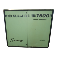
4500P-7500 USER MANUAL SECTION 4
54
FLUID CONTAINMENT
Compressors have a fluid containment pan to collect
fluid leaks or spills. The pan has a drain located on
the air intake side of the machine.
The drain pan on indoor installations should be
plugged.
Outdoor installations require a separate customer
supplied system to allow for the drainage of rainwater
or accumulated compressor fluid.
4.4 COUPLING ALIGNMENT
CHECK
No coupling alignment check is required.
4.5 FLUID LEVEL CHECK
The compressor is shipped fully charged with the
proper amount of fluid. However, it is necessary to
check the fluid level at the time of installation and
during compressor operation. Check the fluid level
when the compressor is in the SHUT DOWN MODE
(fluid level may not be visible when operating), and
by looking at the sight glass on the receiver tank
(See Figure 3-1). The full level is at half the sight
glass. Add fluid if fluid level is not visible in the sight
glass when machine is shut down.
4.6 ELECTRICAL PREPARATION
Interior electrical wiring is installed at the factory.
Required customer wiring should be done by a
qualified electrician in compliance with OSHA,
National Electric Code and/or any applicable local
electrical codes applying to isolation switches, fused
disconnects, etc. Refer to Figures 4-2 and 4-3. Sullair
provides a wiring diagram for use by the installer. An
electrical check should be made to ensure that the
first start-up will be successful. The compressor and
drive should be properly grounded/earthed in
accordance with applicable codes, regulations, and
requirements.
Feeder cables should be sized by the customer/
electrical contractor to ensure that the circuit is
balanced and not overloaded by other electrical
equipment. The length of wiring from a suitable
electrical power source is critical because voltage
drops can adversely effect the performance of the
compressor. Cable sizes may vary considerably so
the mains terminals will accept up to 120 mm
2
(4/0
awg) (75kw) cable.
Feeder cable connections to incoming terminals L1-
1. Air-Cooled
2. Water-Cooled
3. Air Connection 2” NPT
4. Incoming Power Location
5. Condensate Drain 2” NPT
6. Cooling Water Out 1-1/2” NPT
7. Cooling Water In 1-1/2” NPT
8. Alternate Incoming Power Location
Figure 4-2: Connection Locations

 Loading...