4500P-7500 USER MANUAL SECTION 6
60
4. Apply a light film of fluid to the element seal.
5. Install the element into the filter canister.
6. Screw the canister to the filter head. Tighten
to 20 ft·b (27.1 Nm).
7. Restart compressor and check for leaks.
6.6 AIR FILTER MAINTENANCE
Refer to Figure 6-2. Air filter maintenance should
be performed when the maintenance gauge
shows red with the compressor running full load,
or once a year, whichever comes first.
AIR FILTER ELEMENT REPLACEMENT
1. Clean the air filter’s exterior housing.
2. Release the hold-down clips and remove the
end cover.
3. Remove the air filter element by pulling it out
of the housing.
4. Clean the housing interior with a damp cloth.
DO NOT blow dirt out with compressed air.
5. Replace the element.
6. Reassemble in the reverse order.
Figure 6-2: Air Filter Assembly
6.7 SEPARATOR MAINTENANCE
Replace the separator elements when shown by
the WS Controller indications, or after one 1 year,
whichever comes first. The separator elements
must be replaced. DO NOT attempt to clean and
reinstall the separator elements.
SEPARATOR ELEMENT REPLACEMENT
Refer to Figure 6-3. The separator elements
must be changed when WS indications show the
requirement, or once a year, whichever occurs
first. Use the following procedure below to
change the separator:
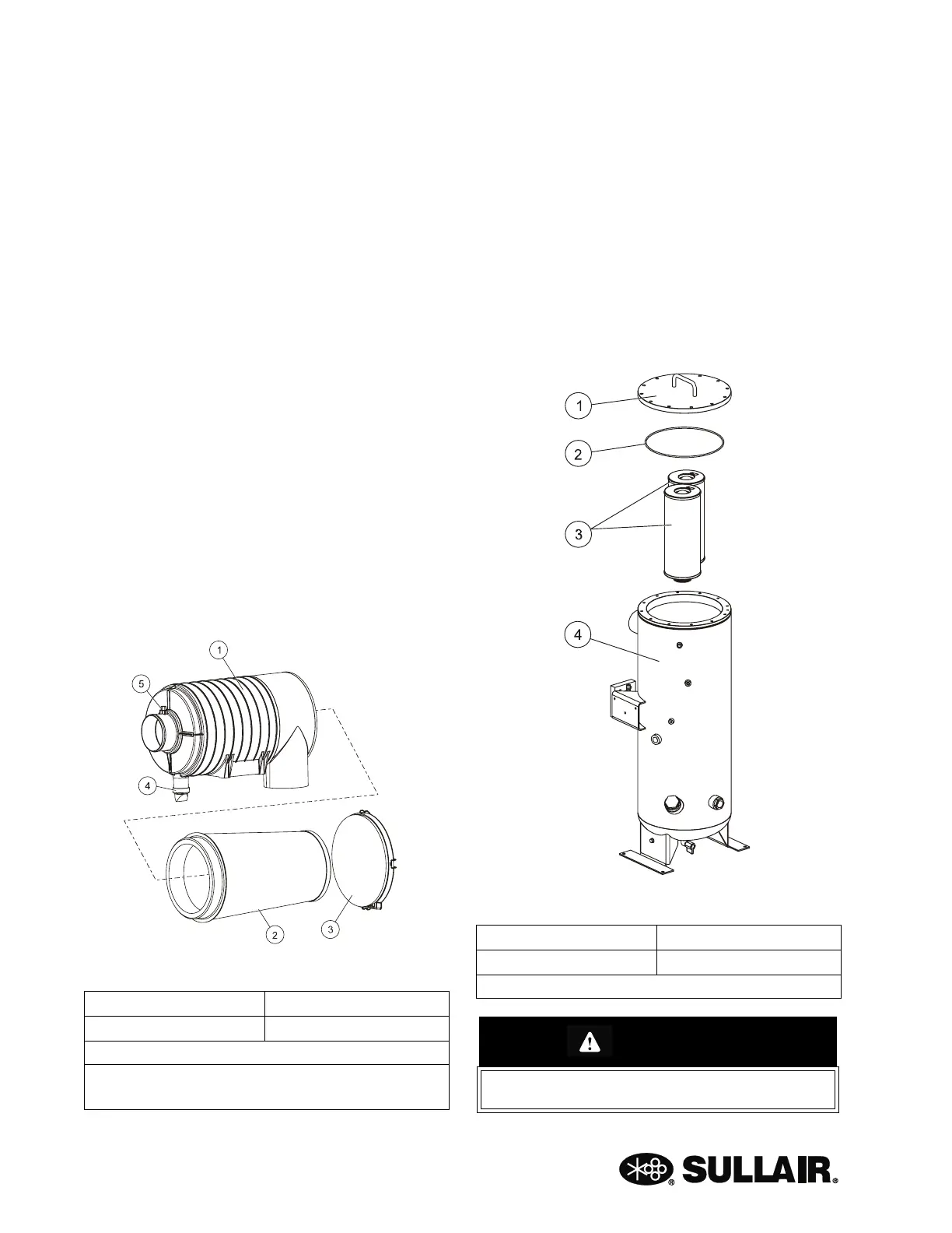
Figure 6-3: Separator Element Assembly
1. Housing 3. Cover
2. Element (I) 4. Vacuator Valve (II)
(I) Element Replacement Kit P/N 02250168-053
(II) Vacuator Valve Replacement Kit
P/N 02250125-376
1. Cover 3. Elements (I)
2. Cover Gasket (I) 4. Receiver Tank
(I) Element Replacement Kit P/N 02250169-993
CAUTION!
Relieve all pressure from the receiver tank
and all compressor lines.
 Loading...


