DE-18 USER MANUAL SECTION 4
38
FULL LOAD MODE, • 70 TO 150 PSIG (4.8-
10.3 BARG)
After five minutes at 1400 RPM, or the engine
coolant temperature reaches 130°F, the controller
will modulate the engine speed between 1400·1840
RPM until the system set pressure is reached.
Simultaneously, the controller sends a signal to the
inlet control solenoid, opening (energizing) the
solenoid valve. The valve directs pressurized oil to
the actuator, which extends its control rod opening
the butterfly valve to ingest air. The same controller
signal is sent to the blowdown solenoid valve,
opening (energizing) the solenoid and allowing LP
pilot air 10 be routed to the pneumatic blowdown
valve diaphragm. The pneumatic force overcomes
the spring force and closes the blowdown.
UNLOAD MODE: > 150 PSIG (10.3 BARG)
If the demand for compressed air falls below supply,
system line pressure (P2) should increase as the
discharge check valve closes. When P2 exceeds set
point pressure (100 psig) the controller will signal the
engine to reduce speed and the inlet control solenoid
to close (de-energizing), routing oil pressure to the
actuator retract position and closing the inlet butterfly
valve. The same signal will close (de-energize) the
blowdown solenoid, removing LP pilot air pressure
from the pneumatic blowdown valve, opening the
valve so that process air will be evacuated to the
silencer.
4.6 COMPRESSOR COOLING
AND SILENCING SYSTEM,
FUNCTIONAL DESCRIPTION
Refer to Figure 4-4, Figure 4-5 and Figure 4-7. As air
is discharged by each compressor stage, it is
sequentially routed to:
• silencer/dampener to reduce noise and pressure
pulsations caused by the compressor.
• heat exchangers to cool the compression process.
• combination separator/drains to remove liquids
condensed in the heat exchangers.
The LP stage silencer is a reactive pipework sized to
dampen lower frequency air pulses, while the HP
stage silencer is a reactive vessel sized to dampen
higher frequency pulses.
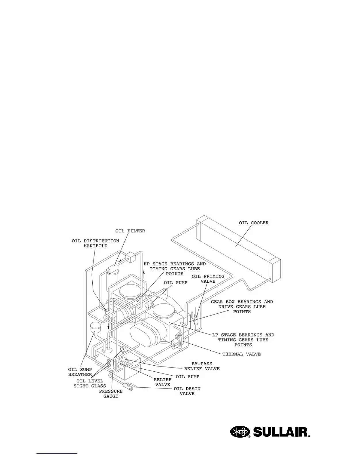
Figure 4-6: Lubrication System