Do you have a question about the Sullair LS-25S and is the answer not in the manual?
Covers general safety guidelines for operating Sullair compressors.
Details required PPE for operating and maintaining the compressor.
Safety measures related to pressure release in air lines.
Precautions to prevent fire and explosion risks.
Guidelines to avoid injury from moving compressor components.
Safety related to hot surfaces, sharp edges, and corners.
Precautions when handling toxic or irritating substances.
Critical safety measures to prevent electrical shock.
Guidelines for safely lifting and handling the compressor.
Safety measures to prevent entrapment in compressor enclosures.
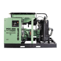
Overview of Sullair rotary screw air compressor benefits.
Identification and overview of major compressor parts.
Functional description of the single-stage, positive displacement compressor.
Functional description of the cooling and lubrication system.
Functional description of the compressed air discharge system.
Description of how the capacity control system regulates air output.
Functional description of the air filter and inlet valve system.
Overview of the Supervisor I control panel and its displays.
Details on user-programmable functions and parameters.
Instructions for proper compressor mounting and foundation.
Guidelines for adequate ventilation and cooling for the compressor.
Recommendations for installing service air piping.
Specific instructions for air-cooled fluid piping installation.
Procedure for checking coupling alignment after shipping.
Instructions on checking the compressor fluid level.
Guidelines for electrical connection and preparation.
Procedure to verify correct motor rotation direction.
Introduction to compressor operation and controls.
Explanation of the function of various controls and indicators.
Step-by-step guide for the first-time compressor start-up.
Procedure for starting the compressor after initial use.
Instructions for properly shutting down the compressor.
Routine checks and general maintenance overview.
Maintenance tasks at initial hours and 1000-hour intervals.
Procedures for fluid changes and separator element replacement.
Procedure for replacing the main fluid filter element.
Procedure for inspecting and replacing air filter elements.
Instructions for replacing primary and secondary separator elements.
Procedure for adjusting the Sullicon control system parameters.
Maintenance and replacement of the thermal valve.
Installation, alignment, and maintenance of the drive coupling.
Procedure for servicing the fluid stop valve.
Maintenance and cleaning of solenoid valves.
Procedure for maintaining the pressure regulator valve.
Maintenance for the minimum pressure/check valve.
Procedure for servicing the blowdown valve.
Maintenance and replacement of the control line filter.
Procedure for replacing flexible coupling gasket rings.
Guide to diagnosing and resolving common compressor problems.
Instructions on how to order replacement parts.
List of recommended spare parts for the compressor.
Illustration and parts list for motor, compressor, and frame components.
Illustration and parts list for the air intake system.
Illustration and parts list for air-cooled remote cooler piping (200-250HP).
Illustration and parts list for air-cooled remote cooler piping (300-350HP).
Illustration and parts list for water-cooled fluid cooling (200-250HP).
Illustration and parts list for water-cooled fluid cooling (300-350HP).
Illustration and parts list for the compressor discharge system.
Illustration and parts list for the Sullicon control system.
Illustration and parts list for the compressor actuator.
Illustration and parts list for the electro-pneumatic control system.
Illustration and parts list for the compressor enclosure.
Illustration and parts list for the unit tubing.
Illustration and list of various warning and identification decals.
Dimensional data for water-cooled models (200HP/150KW).
Dimensional data for water-cooled models (250-350HP).
Dimensional data for air-cooled models (300HP/225KW).
Schematic diagram of the compressor's electrical wiring.
Schematic diagram for Wye-Delta motor starting configuration.
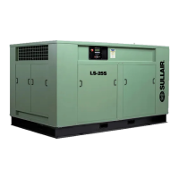
| Model | LS-25S |
|---|---|
| Category | Air Compressor |
| Type | Rotary Screw |
| Power | 25 hp |
| Voltage | 460V |
| Phase | 3 |
| Drive | Direct |