Do you have a question about the Sullair LS-200 and is the answer not in the manual?
General safety principles for compressor operation and maintenance.
Guidelines for using safety gear, including eye, hearing, and body protection.
Procedures for safely releasing system pressure before maintenance.
Precautions against fire hazards, flammable substances, and ignition sources.
Safety measures to avoid contact with rotating components and pinch points.
Warnings about contact with hot surfaces and sharp edges.
Safety information regarding hazardous fluids and air quality for breathing.
Essential safety procedures for electrical installation and maintenance to prevent shock.
Guidelines for safely lifting and handling the compressor unit.
Precautions to prevent accidental entrapment within the compressor enclosure.
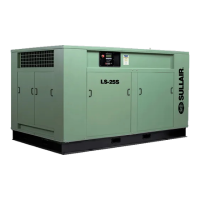
Overview of the Sullair rotary screw air compressor's features and benefits.
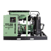
Identification and brief description of the compressor's main assemblies and parts.
Detailed explanation of the rotary screw compressor unit's positive displacement function.
How the cooling and lubrication systems manage fluid and temperature.
Explanation of the system that separates air and fluid after compression.
How the Supervisor Controller manages compressor operation and regulates air delivery.
Functionality of the Electro-Mechanical Control System for air intake regulation.
Description of the air filter and inlet valve mechanism for controlling air intake.
Overview of the instrument panel gauges, indicators, and controls.
Technical data including HP/KW, CFM/M3/MIN, dimensions, and weight.
Recommendations for Sullube fluid changes and maintenance for standard models.
Guidelines for lubricant changes and fluid analysis for 24KT compressors.
Information on using SRF 1/4000 fluid and its maintenance requirements.
Guidance on using the fluid analysis program for optimal maintenance intervals.
Requirements for compressor foundation and secure mounting.
Guidelines for ensuring adequate airflow for stable operating temperatures.
Recommended installation procedures for service air piping, including shut-off valves.
Statement that no coupling alignment is required.
Procedures for checking and maintaining the correct fluid level in the sump.
Steps for electrical connection and checks for electro-mechanical controls.
Steps for electrical connection and checks for Supervisor Controller systems.
Method for verifying correct motor rotation direction for electro-mechanical units.
Method for verifying correct motor rotation direction for Supervisor Controller units.
Introduction to the electro-mechanical control system and its indicators.
Explanation of the purpose and function of various controls and indicators.
Step-by-step guide for the first-time start-up of the compressor.
Procedures for starting the compressor after initial setup.
Steps for safely shutting down the compressor.
Introduction to the Supervisor Controller system and its operation.
Explanation of the purpose and function of controls for Supervisor Controller.
Step-by-step guide for the initial start-up using the Supervisor Controller.
Procedures for starting the compressor with the Supervisor Controller after initial setup.
Steps for safely shutting down the compressor using the Supervisor Controller.
Overview of the minimal maintenance requirements for the air compressor.
Daily checks and observations for proper compressor operation.
Initial maintenance tasks to remove foreign materials from the system.
Maintenance tasks required after the first 1000 hours of operation.
Instructions for greasing motor bearings according to manufacturer recommendations.
Procedures and recommendations for changing compressor fluid (Sullube, 24KT, SRF 1/4000).
Detailed procedures for replacing common parts like filters and elements.
General guidance and initial inspection steps for diagnosing problems.
A comprehensive guide listing symptoms, probable causes, and remedies for common issues.
Overview of components specific to variable speed drive (VSD) compressors.
Explanation of how the control system manages VSD operation and air delivery.
Instructions on how to order replacement parts, including contact information.
A list of recommended spare parts with kit numbers and quantities.
| Model | LS-200 |
|---|---|
| Type | Rotary Screw |
| Power Source | Electric |
| Phase | 3 |
| Air Delivery | 250 - 1150 acfm (depending on model) |
| Pressure | 100 PSIG |
| Voltage | 460V |
| Drive Type | Direct |
| Cooling Method | Air Cooled |
| Weight | 5000 lbs |