Section 8
MAINTENANCE
53
With the lead taped, you may start the compressor
again. Allow the sump pressure to stabilize.
The sump pressure should read 20 to 30 psig (1.4
to 2.1 bar).
Once this is checked, shut the compressor down
once again and reconnect the taped lead and
replace the pressure switch cover. At this time, start
the compressor and cycle the Control System sev-
eral times and re-check all pressure settings and
adjustments.
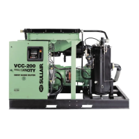
PRESSURE REGULATOR ADJUSTMENT
Start the compressor and adjust the service valve to
maintain service air pressure approximately at five
(5) psi over rated pressure. Turn the inlet valve reg-
ulator adjusting screw until air just begins to escape
from the control air orifice (located at the bottom of
the regulator; refer to Figure 8-6). Lock the adjust-
ing screw in place with the locknut. The regulator is
now properly set.
COMPRESSORS WITH SPIRAL VALVE
Start the compressor and adjust the service valve to
maintain service air pressure approximately at five
(5) psi over rated pressure. Turn the inlet valve reg-
ulator adjusting screw until air just begins to escape
from the control air orifice (located at the bottom of
the regulator). Lock the adjusting screw in place
with the locknut.
Readjust the service valve to maintain service air
pressure approximately one (1) psi over rated pres-
sure. Turn the spiral valve regulator adjusting screw
until air just begins to escape from the control air
DO NOT touch the pressure switch, electrical con
with any part of the body or any un-insulated
metallic object. Severe electrical shock may
occur.
DO NOT touch the pressure switch, electrical
contacts, terminal board or leads with any part of
the body or any un-insulated metallic object.
Severe electrical shock may occur.
Figure 8-6 Regulator Adjustment
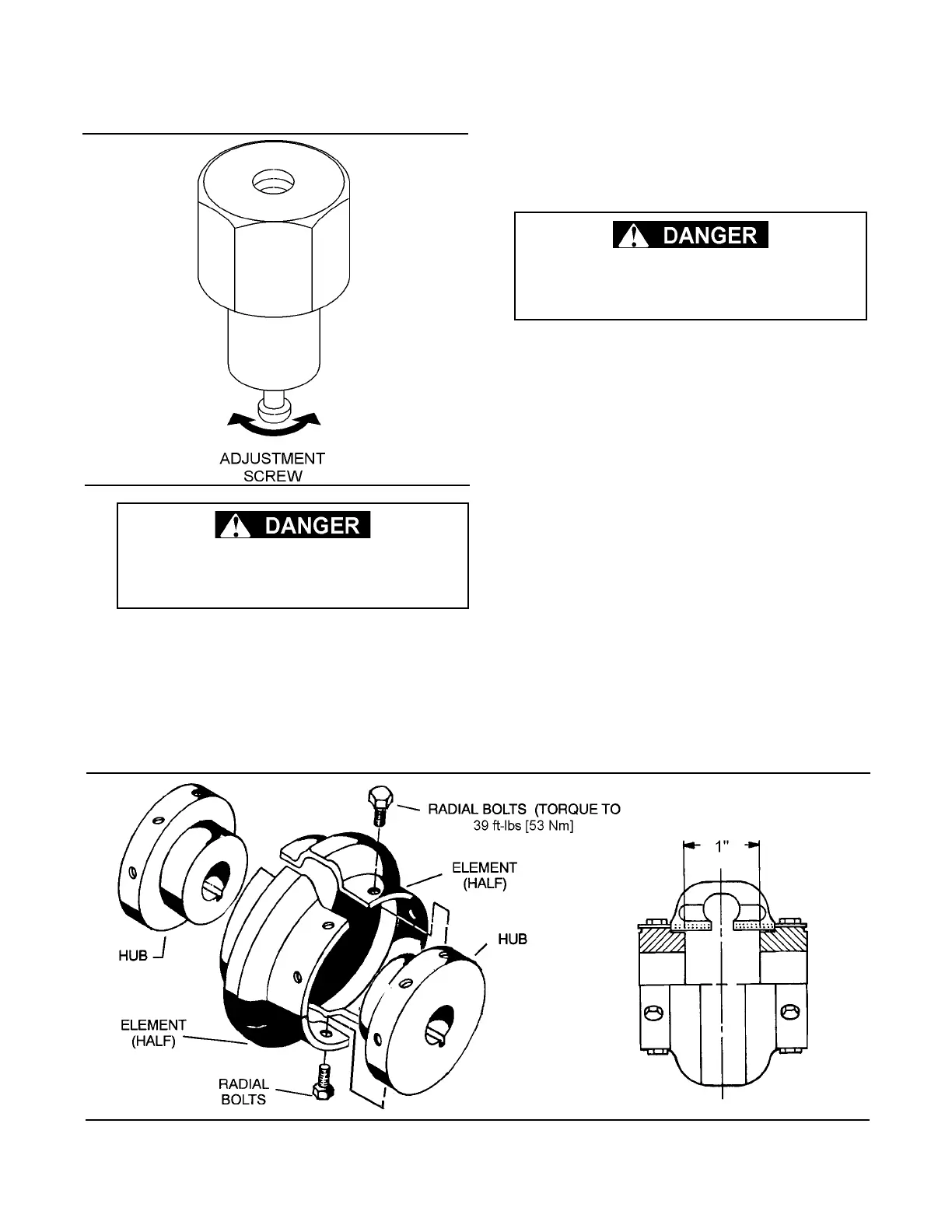
Figure 8-7 Drive Coupling
 Loading...
