Section 2
DESCRIPTION
12
noid valve sends a pneumatic signal to the blow-
down valve. The blowdown valve opens to the
atmosphere, reducing the sump pressure to
approximately 20 to 30 psig (1.4 to 2.1 bar). The
minimum pressure check valve prevents line pres-
sure from returning to the sump.
When the line pressure drops to the low setting
(cut-in pressure; usually 100 psig [6.9 bar] on low
pressure [“L”] compressors; 125 psig [8.6 bar] on
high pressure [“H”] compressors; 150 psig [10.3
bar] on [“HH”] compressors; and 175 psig [12.0
bar] [“XH”]. Supervisor energizes the solenoid
valve and allows the blowdown valve to close. The
re-energized solenoid valve again prevents line
pressure from reaching the inlet control valve.
Should the pressure begin to rise, the pressure reg-
ulator will resume its normal function as previously
described.
AUTOMATIC OPERATION
For applications with varied periods of time when
there are no air requirements, Supervisor’s AUTO-
MATIC mode allows the compressor to shutdown
(time delayed) when no compressed air require-
ment is present and restart as compressed air is
needed.
2.7 CONTROL SYSTEM, FUNCTIONAL DESCRIP-
TION- ELECTRO-MECHANICAL
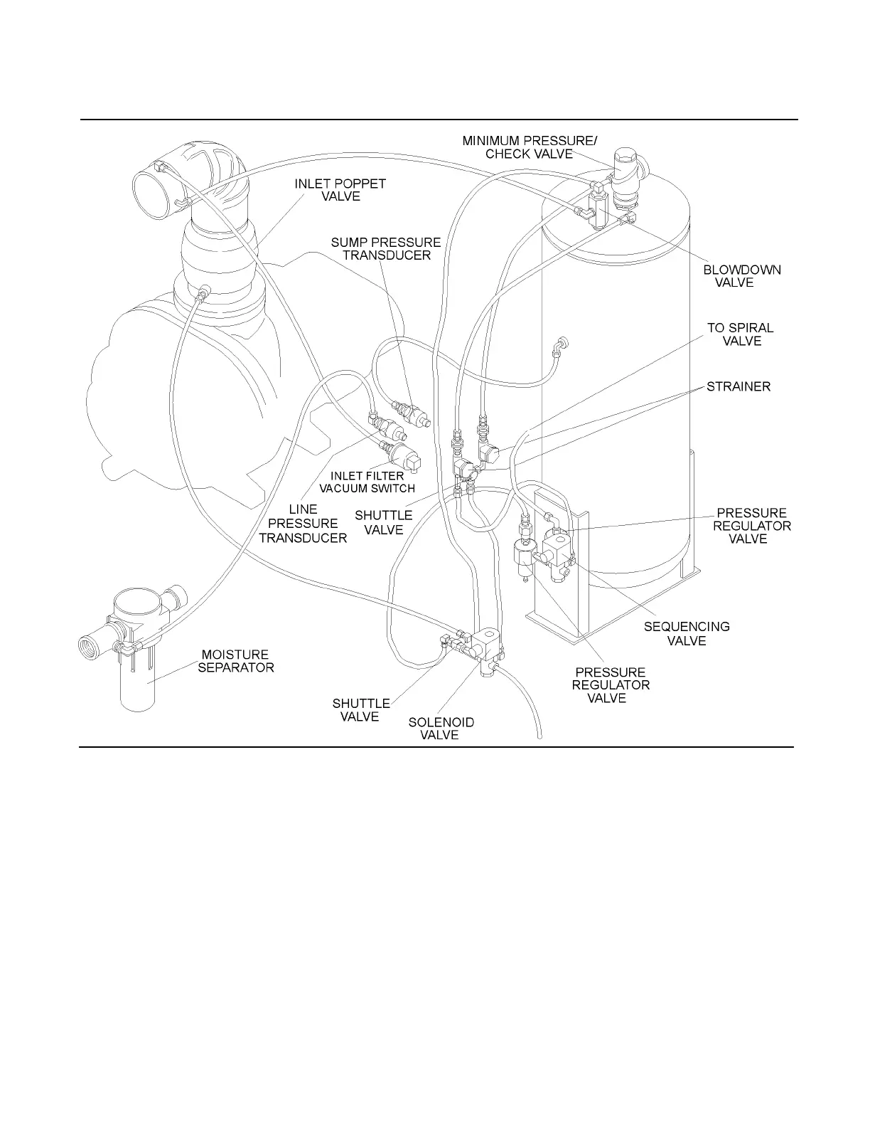
Refer to Figure 2-3C. The purpose of the compres-
sor Control System is to regulate the compressor
air intake to match the amount of compressed air
Figure 2-3B Control System with Supervisor Controller (with Spiral Valve)
 Loading...
