20 COMPONENT DESCRIPTION
4.5.2 OIL RETURN LINE
The oil that is removed by the air/oil separator gravitates to the bottom of the air/oil separator and is
the compressor.
4.5.3 OIL FILTER
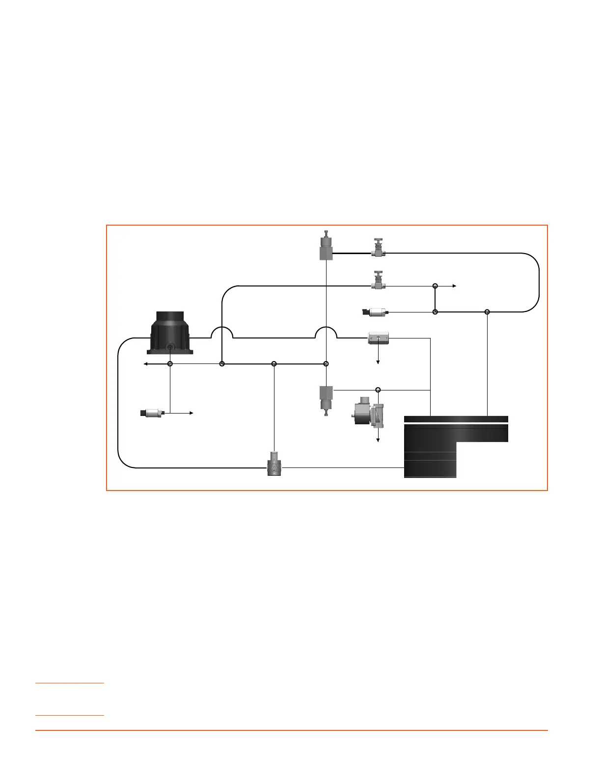
4.6 CAPACITY CONTROL SYSTEM
The control system is designed to match air supply to air demand and to prevent excessive discharge
pressure when the compressor is operating but air is not being used. Control of air delivery is accomplished
by inlet valve regulation and engine speed control as directed by the adjustable discharge pressure regulator
valve(s) .
SPEED
PRESSURE
TRANSDUCER
NOTE:
1. SOLID PIPE CONNECTIONS REPRESENTED BY THIN LINES.
2. UNLESS SPECIFICALLY NOTED, INDIVIDUAL PART ORIENTATIONS ARE FOUND ON ASSEMBLY DRAWINGS
3. UNLESS SPECIFICALLY NOTED, IMAGES OF PARTS ARE FOR REPRESENTATION ONLY, ACTUAL PARTS MAY VARY IN APPEARANCE.
HIGH PRESSURE
REGULATOR
LOW PRESSURE
REGULATOR
COLD START SOLENOID
(OPTIONAL ON SOME MODELS)
VENT DOWN TO
ATMOSPHERE
RECEIVER TANK
INLET VALVE
BLOWDOWN VALVE
PRESSURE
SENSOR
START/RUN
VALVE
VENT DOWN TO
ATMOSPHERE
VENT DOWN TO
ATMOSPHERE
VENT DOWN TO
ATMOSPHERE
VENT DOWN TO
ATMOSPHERE
RECIRCULATION
VALVE
HIGH/LOW
VALVE
D
C
1
3
4
5
A
B
C
D
E
F
5
3
2
1
F
E
B
A
4
2
D
JDS
FIRST USED ON:
3RD ANGLE
PROJECTION
1201 West US Highway 20, Michigan City IN 46360
1-800-438-6203
SHEET
SCALE:
TOLERANCES AS FOLLOWS:
REV
DESCRIPTION
THIS DRAWING AND ALL INFORMATION THEREIN IS THE PROPERTY OF SULLIVAN-PALATEK, INC. IS CONFIDENTIAL AND MUST NOT BE MADE PUBLIC OR COPIED.
WWW.SULLIVANPALATEK.COM
SULLIVAN-PALATEK
CHECKED BY:
DATE:
DATE:
DRAWN BY:
ANGLES: + OR - 1/2 DEG.
DIMENSIONS ARE IN INCHES
UNLESS OTHERWISE NOTED
X.XXX + OR - 0.005
X.XX + OR - 0.020
DECIMAL: X.X + OR - 0.050
MATERIAL:
IT IS LOANED SUBJECT TO RETURN UPON DEMAND, IS NOT TO BE USED DIRECTLY OR INDIRECTLY IN ANYWAY DETRIMENTAL TO SULLIVAN-PALATEK'S INTEREST.
DRAWING NO:
SIZE
1 OF 1
6/22/21
00
CD-00032
DUAL PRESSURE
CONTROL DIAGRAM
The following overview explains the operation of the control from a condition of “no load” to a condition of
“full capacity” at working pressure. For the working pressure range of your machine, refer to applicable data
The inlet valve cylinder pressure chamber is pneumatically connected to the
dry side of the receiver via the pressure regulator valve. When the receiver tank pressure is below the set
point of the regulator valve no pressure will exist in the inlet valve cylinder. Under these conditions, the inlet
valve will remain wide open, causing the compressor to deliver full capacity.
As the demand for air decreases, the receiver pressure will rise, and when this pressure level exceeds the set
point of the pressure regulator valve, control signal pressure will be allowed to enter the inlet valve chamber,
which in turn will move the modulating piston and the valve plate to a closed condition, thereby throttling
the incoming air.A pressure transducer separate throttle air cylinder controls engine speed. The air cylinder
is spring loaded in the full speed position when there is no air signal from the pressure regulator valve.
Whenever less than full capacity is required, receiver pressure increases, thereby opening the pressure
regulator, which allows a pressure signal to enter the throttle air cylinder and reduce the engine speed until it
matches the air requirements from 100% down to 60%. From 60% down to 0% both engine speed reduction
and inlet valve modulation act together to reduce air output.
NOTE! The compressor can only produce its maximum rating of air ow at rated pressure (rated CFM at rated psig).
If the tank pressure continues to decrease when the machine is at full speed and the inlet valve fully open, a
larger capacity compressor or multiple compressors may be required for the customer’s job needs.
 Loading...