5 Installation Procedure
16
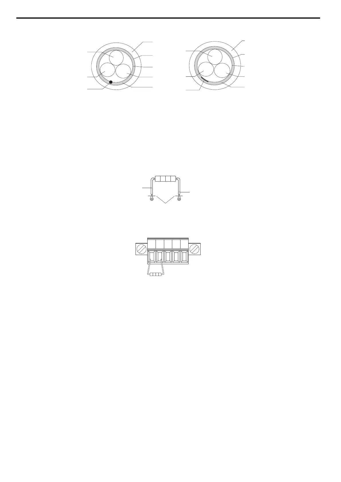
Figure 14
Figure 14 Cable Diagram
■ Terminal Resistor Connection
When the CC-Link Option is the last station connected in a CC-Link network, the terminal resistor needs to be set to that CC-Link Option. Follow
the instructions below.
1. Cut the terminal resistor tube as shown.
Note: For the terminal resistor, either use what is already built into the master unit, or use a standard-market resistor of 110 Ω, ±5% (1/2 W).
Figure 15
Figure 15 Terminal Resistor
2. Loosen the attachment screw and insert the terminal resistor described in the first step between terminals DA and DB.
Note: Make sure that the option cover is put back on after wiring is complete.
Figure 16
Figure 16 Terminal Resistor Wiring
A – sheath F – drain (concentrated)
B– shield G–DB
C – aluminum tape H – DA
D – DG I – drain (spread out)
E – ground
A
B
C
D
E
H
G
F
white
blue
yellow
A
B
C
D
E
H
G
I
white
blue
yellow
umper
cut here
cut
DA DB DG SLD SLD