9 Troubleshooting
23
9 Troubleshooting
◆ Drive-Side Error Codes
Drive-side error codes appear on the drive’s LED operator. Causes of the errors and corrective actions are listed in Table 14.
For additional error codes that may appear on the LED operator screen, refer to the HF-520 Technical Manual.
■ Faults
Both bUS (CC-Link Option Communication Error) and EF0 (External Fault Input from the CC-Link Option) can appear as an alarm or as a fault.
When a fault occurs, the digital operator ALM LED remains. When an alarm occurs, the digital operator ALM LED flashes.
If communication stops while the drive is running, answer the following questions to help remedy the fault:
• Is the CC-Link Option properly installed?
• Is the communication line properly connected to the CC-Link Option? Is it loose?
• Is the PLC program working? Has the PLC CPU stopped?
• Did a momentary power loss interrupt communications?
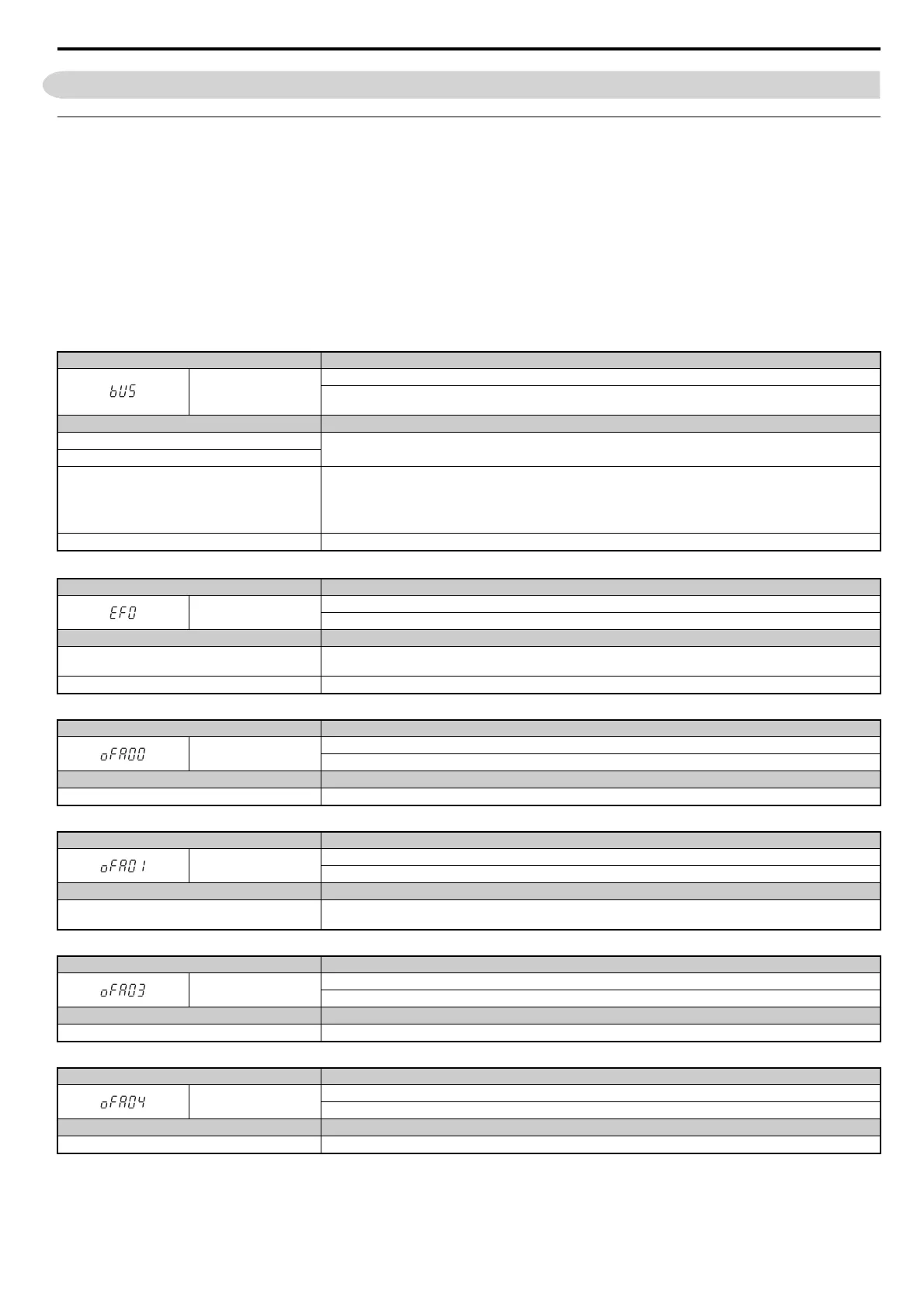
Table 14 Fault Display and Possible Solutions
LED Operator Display Fault Name
bUS
CC-Link Option Communication Error
After establishing initial communication, the connection was lost.
Only detected when the run command or frequency reference is assigned to the option (b1-03 = 3 or b1-02 = 3).
Cause Possible Solution
Master controller (PLC) has stopped communicating.
Check for faulty wiring.
Correct any wiring problems.
Communication cable is not connected properly.
A data error occurred due to noise
Check the various options available to minimize the effects of noise.
Take steps to counteract noise in the control circuit wiring, main circuit lines, and ground wiring.
If a magnetic contactor is identified as a source of noise, install a surge absorber to the contactor coil.
Use cables recommended by Sumitomo, or another type of shielded line. The shield should be grounded on the PLC side and
on the CC-Link Option side.
CC-Link Option is damaged. If there are no problems with the wiring and the error continues to occur, replace the CC-Link Option.
LED Operator Display Fault Name
EF0
External Fault Input from CC-Link Option
The alarm function for an external device has been triggered.
Cause Possible Solution
An external fault is being sent from the master controller
(PLC).
Remove the cause of the external fault.
Reset the external fault input from the PLC device.
Problem with the PLC program Check the program used by the PLC and make the appropriate corrections.
LED Operator Display Fault Name
oFA00
CC-Link Option Fault (port A)
CC-Link Option is not properly connected.
Cause Possible Solution
Non-compatible option connected to the drive Connect an option that is compatible with the drive.
LED Operator Display Fault Name
oFA01
CC-Link Option Fault (port A)
CC-Link Option is not properly connected.
Cause Possible Solution
Problem with the connectors between the drive and CC-
Link Option
Turn the power off and check the connectors between the drive and CC-Link Option.
LED Operator Display Fault Name
oFA03
CC-Link Option Fault (port A)
CC-Link Option self-diagnostics error.
Cause Possible Solution
CC-Link Option hardware fault Replace the CC-Link Option.
LED Operator Display Fault Name
oFA04
CC-Link Option Fault (port A)
CC-Link Option Flash write mode
Cause Possible Solution
CC-Link Option hardware fault Replace the CC-Link Option.