8 CC-Link Data Table
22
■ Drive → PLC
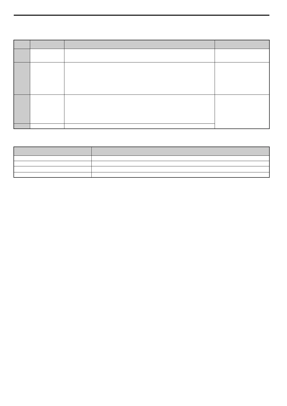
Table 12 Remote Register (Drive → PLC)
How o1-03 Determines Data in RW
R1
Table 13 RW
R1
Data
Note: Refer to the HF-520 Technical Manual for more details on parameter settings.
Remote
Register
Name Description Check Flag
RW
R0
Monitor Data
• Monitor data is stored according to RW
W0
(Monitor Code).
• Monitor data is updated while RYC (monitor execute request flag) is enabled. RXC (during monitor)
remains on as data is updated.
RXC (while monitoring)
RW
R1
Output Frequency
• Output frequency has been set without any errors. Set in the units specified by o1-03 (Frequency Reference
Setting Units).
Example: When o1-03 = 0, the frequency is displayed in Hz.
When o1-03 = 2, the frequency is displayed as min-1.
• When operating with a PG encoder, the motor revolutions are stored as min-1. Here, RXB (actual motor
rotations) is enabled.
• When RYB (motor rotations / output frequency switch) is enabled, the value stored to this register changes
from the number motor rotations to the output frequency.
–
RW
R2
Response Code
• Sets 00H when there are no problems with RW
W2
(Command Code) and RW
W3
(Write Data).
• Sets 01H through 03H if an error occurs.
• Response Code:
00h: Normal
01h: Write-mode error (attempted to write during run, etc.)
02h: Command code error
03h: Data setting range error
RXF (Command Code Execute
Complete)
RW
R3
Read Data Data is set according to the command code.
Frequency Reference Setting and Display Units
(o1-03)
Frequency Reference Data Contents (RW
R1
)
0 Hz (output frequency)
1 % (percent of maximum output frequency)
2
min
-1
(calculated from the maximum output frequency and the number of motor poles)
3 User-set (according to parameter o1-10 and o1-11)