9 Troubleshooting
26
■ Faults when running multiple drives
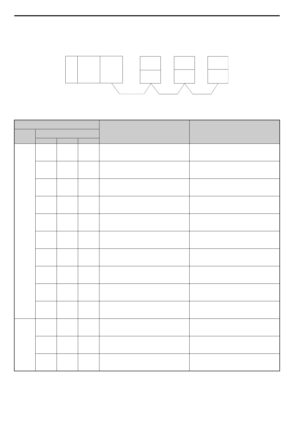
The example below demonstrates how to read the LED display on the CC-Link Option to determine the cause of a fault and the corrective action to
take when multiple drives are running from the same network. The example assumes that SW, M/S, and PRM on the master device are all off,
indicated that the master device is operating normally.
Figure 18
Figure 18 Connecting Multiple Drives on the Same Network
Table 17 LED Fault Display for CC-Link Option with Multiple Drives
: On / : Flashing / ×: Off / ∗: Either on or off
LED Status
Cause Corrective Action
Master
Remote Device Addresses
(CC-Link Option)
Station 1 Station 2 Station 3
TIME
LINE
or
TIME ×
LINE
L.RUN
SD
RD
L.ERR ×
L.RUN
SD
RD
L.ERR ×
L.RUN
SD
RD
L.ERR ×
Normal operation –
L.RUN ×
SD ×
RD ×
L.ERR ×
L.RUN
SD
RD
L.ERR ×
L.RUN
SD
RD
L.ERR ×
The CC-Link Option for the first station is not properly
installed.
Make sure the CC-Link Option and drive are connected
together properly.
L.RUN ∗
SD ∗
RD ∗
L.ERR ∗
L.RUN
SD
RD
L.ERR ×
L.RUN
SD
RD
L.ERR ×
The CC-Link Option for the first station is damaged (most
often all LEDs are out).
Note: Sometimes and error will appear on the
drive’s LED operator
Replace the CC-Link Option.
L.RUN
SD
RD
L.ERR ×
L.RUN ×
SD ∗
RD ∗
L.ERR ×
L.RUN ×
SD ∗
RD ∗
L.ERR ×
Because L.RUN after Station 2 is off, either the comm. line
between Station 1 and Station 2 is disconnected, or the
terminal block has come loose.
Make sure components are connected correctly, using the
LEDs as a guide to indicate a proper connection.
L.RUN ×
SD ∗
RD ∗
L.ERR ×
L.RUN ×
SD ∗
RD ∗
L.ERR ×
L.RUN ×
SD ∗
RD ∗
L.ERR ×
Comm cable has short-circuited
Look for any short-circuits along the communication lines
and fix any problems.
L.RUN ×
SD ∗
RD ∗
L.ERR ∗
L.RUN ×
SD ∗
RD ∗
L.ERR ∗
L.RUN ×
SD ∗
RD ∗
L.ERR ∗
Comm cable is not wire properly
Check the wiring for the CC-Link Option terminal block
and fix and mistakes.
L.RUN ×
SD ∗
RD
L.ERR ×
L.RUN
SD
RD
L.ERR ×
L.RUN ×
SD ∗
RD
L.ERR ×
The CC-Link Options for Station 1 and Station 3 have been
assigned the same address.
Enter the correct station address and cycle power.
L.RUN
SD
RD
L.ERR ×
L.RUN ×
SD ×
RD
L.ERR ×
L.RUN
SD
RD
L.ERR ×
The CC-Link Option for Station 2 has a different comm speed
setting than the master device.
Set the correct communication speed and cycle power.
L.RUN
SD
RD
L.ERR ×
L.RUN
SD
RD
L.ERR ×
L.RUN
SD
RD
L.ERR
The settings for the CC-Link Option connected to Station 3
were changed without cycling power.
Return any incorrect settings to their original values and
cycle power.
Enter the proper settings and cycle power.
L.RUN ×
SD ×
RD
L.ERR
L.RUN
SD
RD
L.ERR ×
L.RUN
SD
RD
L.ERR ×
Parameters related to the CC-Link Option (F6-10, F6-11) for
Station 1 are set outside the acceptable range.
Set F6-10 and F6-11 correctly and cycle power.
TIME ×
LINE ×
or
TIME
LINE ×
L.RUN
SD
RD
L.ERR ×
L.RUN
SD
RD
L.ERR
L.RUN
SD
RD
L.ERR ×
The CC-Link Option connected to Station 2 is experiencing
noise interference (L.RUN is sometimes off).
Make sure that the CC-Link Options, drives, and master
device are all grounded properly.
L.RUN
SD
RD
L.ERR ×
L.RUN
SD
RD
L.ERR
L.RUN
SD
RD
L.ERR
Noise interference along the cable running between Station 2
and Station 3. (L.RUN is sometimes off)
Reconnect the comm line to the SLD terminal on the CC-
Link Option.
Also make sure that all power cables are properly separated
from comm lines (at least 100 mm away).
L.RUN
SD
RD
L.ERR ×
L.RUN
SD
RD
L.ERR ×
L.RUN
SD
RD
L.ERR
Terminal resistor not connected.
(L.RUN is sometimes off)
Set up the final station in the series for terminal resistor.
Power
supply
CPU
Master
device
Station 1
DRIVE
Station 2
DRIVE
Station 3
DRIVE
CC-Link
Option
CC-Link
Option
CC-Link
Option
 Loading...
