2.19
SECTION 2 - SPRAYER OPERATION
5. With all BOOM ON/OFF switches turned ON, hold the manual pressure adjust switch one way
or the other in order to fully open the motorized regulator valve and obtain maximum operat-
ing pressure with full agitation. (The regulator valve is fully opened when the pressure stops
increasing and starts to decrease).
6. Adjust manual valve D or Q (agitator control):
a. Partially close manual valve D or Q to increase maximum operating pressure.
b. Under normal spraying conditions, manual valve D or Q should be fully open.
7. If maximum operating pressure is still too low, follow pump adjusting procedure previously
outlined.
8. With all BOOM ON/OFF switches turned ON, hold the manual pressure adjust switch the
other way in order to fully close the motorized Regulator Valve and obtain minimum operat-
ing pressure. (The regulator valve is fully closed when the pressure stops decreasing and
starts to increase).
9. With all spray BOOM ON/OFF switches turned ON, hold the manual pressure adjust switch to
obtain required operating pressures necessary for desired application rate.
10. Disengage tractor hydraulic system or PTO system.
HELPFUL HINTS FOR 450 CONTROL PROGRAMMING
1. Write down meter cal, valve cal, speed cal, and boom cal numbers in manual for quick, easy reference.
2. If any component fails and is replaced calibration will change and must be updated.
3. Disconnect console before jump starting, charging battery or welding on equipment.
4. Suspension type fertilizers and slurry mixtures will reduce the life of plastic parts in ow meter and
control valve. Check rotor and hub frequently for worn parts. Excessive wear will affect accuracy.
5. Summers Manufacturing uses only standard close valves (C-sd).
6. SP1 is for wheel drive speed sensor. SP2 is for GPS, radar and interface cable speed sensors.
7. If console is ashing “CAL” it has not received enough calibration input to function.
8. To change some settings the console must be cleared. Data from Hint 1 will be useful in this case.
NOTE!
SUMMERS MFG. CO. RECOMMENDS THAT THE OPTIONAL COMPUTERIZED
CONTROL CONSOLE BE MOUNTED TO A SECURE SUPPORT INSIDE THE CAB
OF THE SPRAY MACHINE.
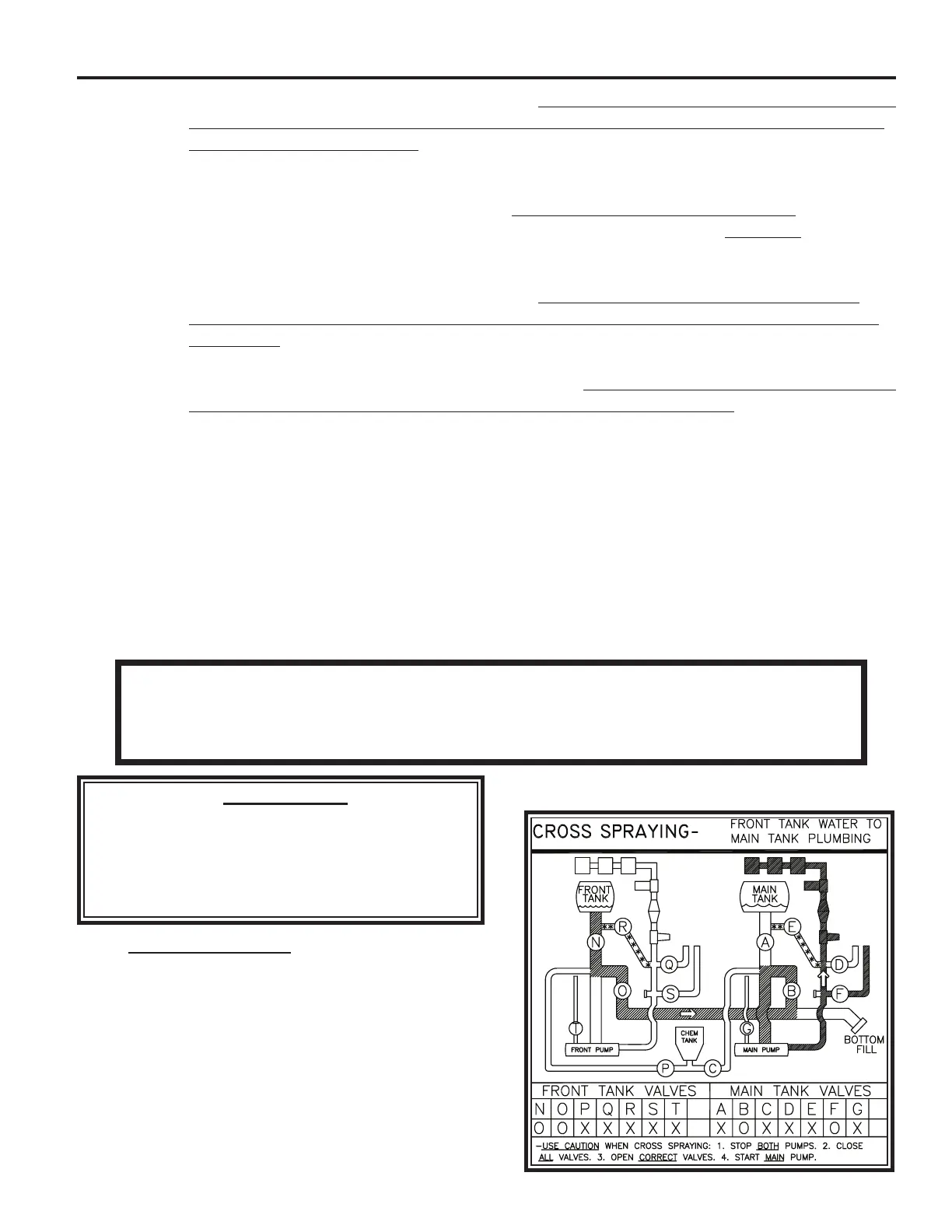
5. CROSS SPRAYING – Front Tank Water to Main
Tank Plumbing. (If you do not have a dual tank
sprayer, proceed to Step 7).
This allows the operator the ability to supply the boom
normally used for the main tank with spray solution
from the front tank.
A. Set up for Front Tank Water to Main Tank Plumb-
ing – Cross Spraying.
IMPORTANT!
OPERATOR MUST PAY CAREFUL ATTEN-
TION WHEN CROSS SPRAYING TO INSURE
THAT SPRAY SOLUTION IS GOING TO ITS
DESIRED LOCATION.