SECTION 6 - OPTION NOTES AND INSTRUCTIONS
6.8
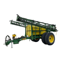
6.11. BOTTOM FILL FLOW METER PACKAGE
Bottom fi ll fl ow meter is installed in the suction side of the sprayer plumbing between the bottom fi ll shut off
valves and the tank bottom suction lines. It is used to provide an indication of the amount of liquid entering
the tank. Its accuracy is plus or minus 2%.
Flow meter installation.
1. Remove tank supply line from end of plumbing fi ttings.
2. Mount fl ow meter in line and install suction line. Flow meter should be rotated or adjusted to obtain the
best possible view of the display. If sprayer has a rinse system the tank selector ball valve will be mounted
between the fl ow meter and the fl uid tanks.
3. Install bolt plate to nearest sprayer cross member.
4. Install bushing bracket to bolt plate.
5. Install threaded fl ow meter bracket to bushing bracket and to fl ow meter.
6. Tighten all fi ttings and check for interference and ease of operation.
6.12. CLEAN LOAD PACKAGE
To install a Cleanload on a Summers Pull-Type Sprayer
1. Locate the front most elbow on pump discharge (plumbing attached to pump that feeds the booms) plumb-
ing. Install tee, clamp, gasket, ball valve, and hose barb fi tting. Ball valve and fi tting are directed to the
front of machine. Existing plumbing will connect to rear facing port on tee.
2. Mount cleanload with bracket to inside right hitch side frame using large u-bolt.
3. Attach the short piece of hose from inlet ball valve to inlet side of chemical eductor and tighten hose
clamps.
4. Locate and drill a 3” diameter hole in the top of main tank near the front and center. The fi tting should be
in an area of the tank that will allow it to seal.
5. Install 2” bulkhead and fi ttings in the top of the tank.
6. Install hose and clamps connecting Cleanload eductor to top of tank.
7. Use extra 2” rubber hose inside tank to drop down lower into the tank. This will help to reduce foaming
when adding chemicals. The hose may need to be perforated near the tank top fi tting to prevent siphoning.
Cleanload Operating Procedure
Loading
1. All Cleanload valves must be closed prior to starting. Inlet ball valve, knife valve, and hopper rinse ball
valve.
2. Open lid to check for foreign objects which may hinder performance or contaminate the system.
3. Close and lock lid by turning cover clockwise.
4. Divert pump fl ow to cleanload inlet line (open valves “C” or “P”). A pressure of 30 PSI minimum and 150
PSI maximum must be used. Highest pressures increase the eduction rate and available wand suction.
5. Open knife valve located on the bottom of hopper by pushing handle in.
6. Unlock and open lid slowly by turning cover counterclockwise.