www.sunhydraulics.com ©2017 Sun Hydraulics Corporation 5
XMD User Manual
Installation Orientation
1. The controller should be mounted to a at surface.
2. The bracket can be mounted horizontally or vertically.
3. Provide sucient clearance from moving parts.
4. Do not mount in a location that will result in ambient tem-
peratures greater than specied operational temperature
limits.
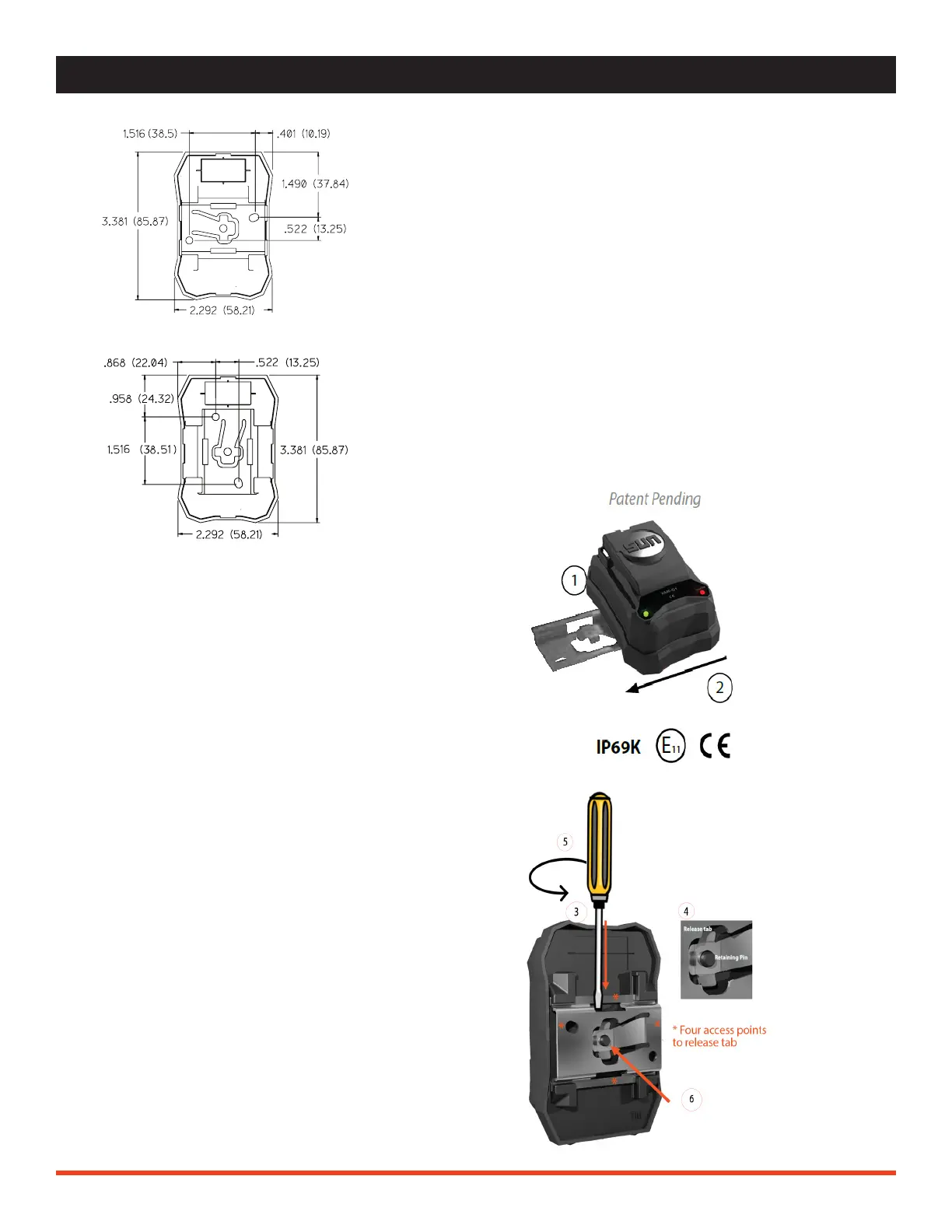
NOTE: Dimensions are in inches (mm).
XMD INSTALLATION / REMOVAL
XMD Installation
1. Mount the bracket to a at surface using the
included hardware, 2x #8-32 x 1/2 T18-8 stainless
screws. Recommended torque is 22 in-lbf.
2. Once the location for the XMD is known, line up
the bracket edges to the XMD and slide it into place
until the release tab is secured over the retaining
pin.
XMD Removal
3. Insert a small athead screwdriver into 1 of 4 access
points.
4. Slide the athead tip of the screwdriver under the
release tab.
5. Twist the screwdriver in order to raise the release
tab over the retaining pin.
6. While applying pressure to the release tab, slide the
controller o of the mounting bracket.

 Loading...