12 Sun Fire V215 and V245 Servers Getting Started Guide • September 2006
■ Fan Fault (amber) – when on, indicates a fan failure event occurred
■ PSU Fault (amber) – when on, indicates that a power supply failure event
occurred
■ Overtemperature (amber) – when on, indicates that a temperature failure event
occurred
* Indicator is provided on the front and rear of the chassis.
Front USB Ports
The Sun Fire V215 server has one USB port (Port 2) on the front panel. The Sun Fire
V245 server has two USB ports (Ports 2 and 3) located on the front panel. The USB
ports on the front panel on the Sun Fire V245 server cannot be used for keyboard or
mouse input devices. With cable lengths of more than 2 meters or for a UDES USB
device, these ports will only support USB 1.1. With cable lengths shorter than 2
meters, these ports will support USB 2.0.
Rear Panels
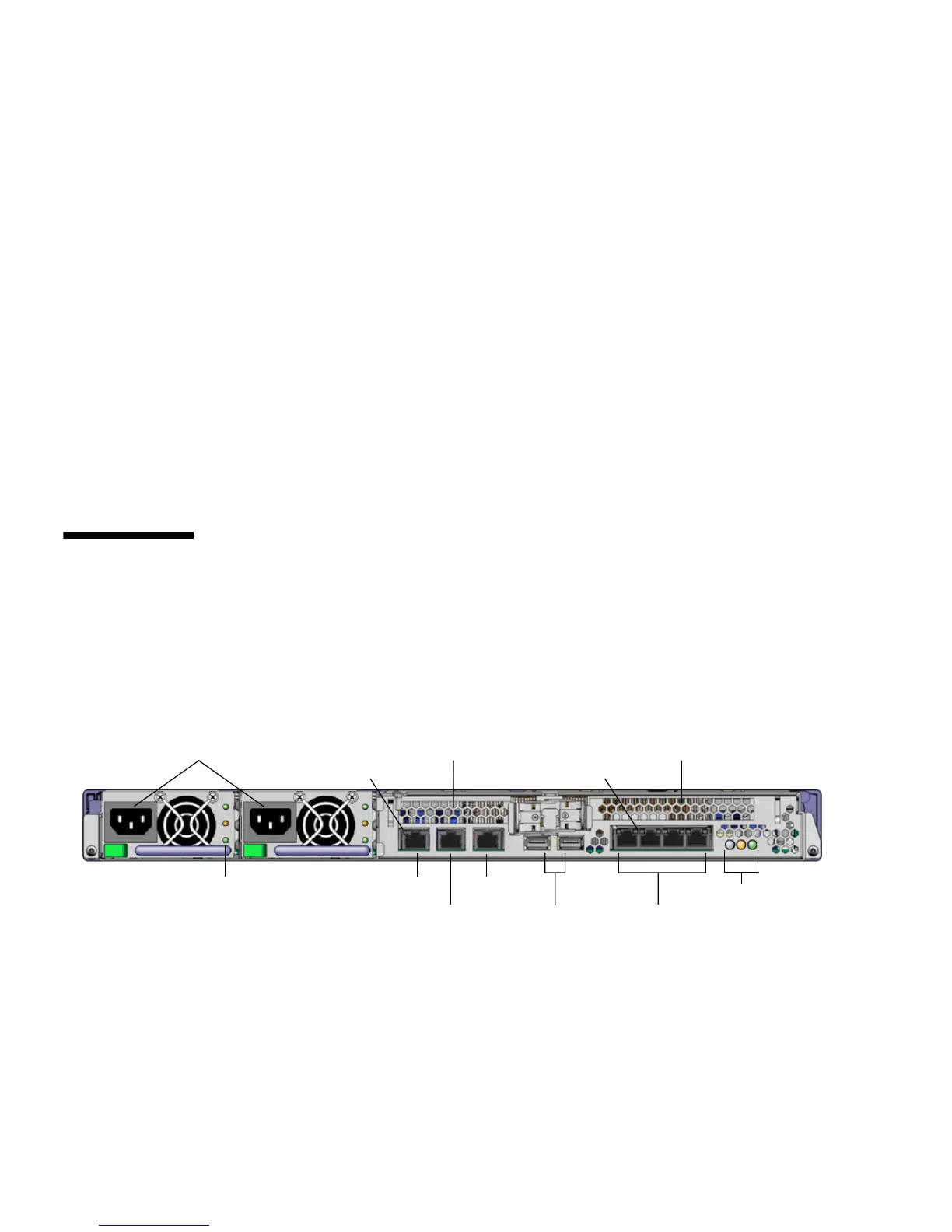
Before you attach and route the cables, become familiar with the location of the
power inlets and I/O ports on the back of the servers.
FIGURE 3 shows the rear panel
for the Sun Fire V215 server, and
FIGURE 4 shows the rear panel for the Sun Fire V245
server.
FIGURE 3 Sun Fire V215 Server Rear Panel
Power inlets
NET MGT
PCI-E slot 0
SER MGT
Ethernet
connectors
USB
SER TTYBPSU indicators
System
indicators
PCI-X slot 1
0
3
2
1
Network indicator
Ethernet indicators






 To Next Page