Introducing the Sun Fire V215 and V245 Servers 13
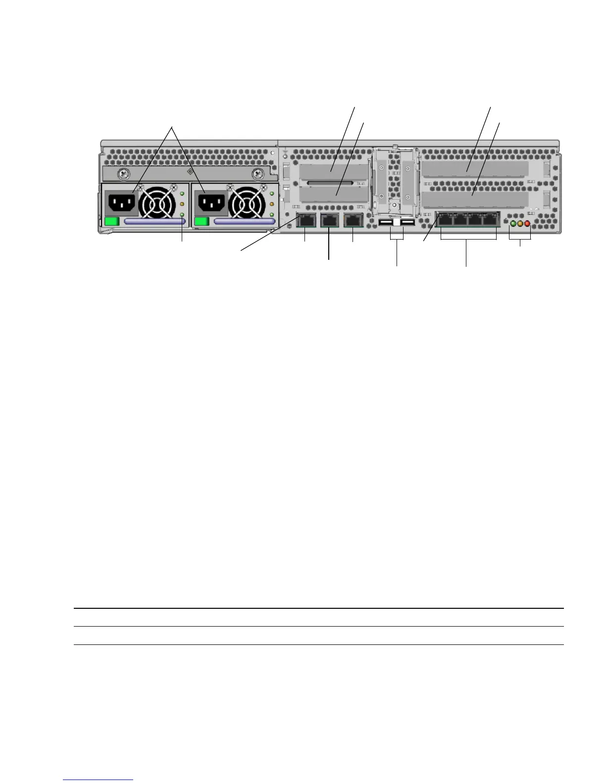
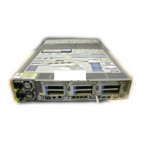
FIGURE 4 Sun Fire V245 Server Rear Panel
Power Inlets
The Sun Fire V215 and V245 servers can have one or two power inlets, one for each
power supply unit (PSU). As long as the server is connected to a power source, the
server is in Standby power mode. The only way to turn the server fully off is to
remove the server from the power source by unplugging the power cable.
Do not attach power cables to the power supplies until you have finished connecting
the data cables and have connected the server to a serial terminal or a terminal
emulator. When the power cables are connected, the server goes into Standby mode,
and the SC boots. System messages can be lost if the server is not connected to a
terminal at this time.
The Sun Fire V245 and V215 servers can have dual redundant PSUs. Each PSU has
three status indicators that tell you if the PSU is active, if the PSU has an internal
error, or if the PSU is ready to be removed.
TABLE 8 includes summaries of the function of the indicators.
TABLE 8 Power Supply Unit Indicators
OK (green) Fault (amber) AC (green) PSU Condition
Off Off On Power is present, and PSU is in standby mode.
Power inlets
PCI-E slot 2
System
indicators
NET MGT
SER MGT
Ethernet
connectors
USB
SER TTYBPSU indicators
0
3
2
1
PCI-E slot 0
PCI-X slot 3
PCI-X slot 1
Ethernet
indicators
Network
indicator






 To Next Page