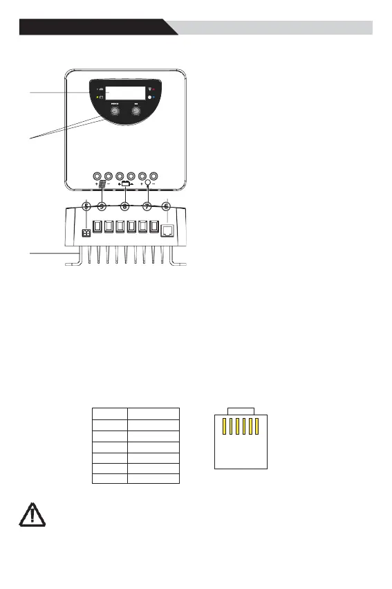
4.1 Structure & Characteristics
③
④
②
①
4.2 Temperature Sensor
①Heat Sink
—dissipate controller heat
②Plastic Case
—Internal protection
③LED & LCD
— Display settings and operating status,
system parameters
④Key: MENU、OK
—Set and view the operating parameters
⑤Temperature Sensor Port
—Collect temperature information,
Temperature
compensation.
⑥RJ11 interface
—Connecting monitoring devices
⑦ Load Terminals
—Connected load.
⑧Battery Terminals
—Connect the battery.
⑨Solar module terminals
—Connected solar modules.
To collect battery temperature data for temperature compensation so the controller can accurately charge
the battery. The temperature sensor is connected via interface 5.
If the external temperature sensor is not connected or damaged, the controller defaults to the internal
temperature information.
The controller is shipped with an 80 mm long cable temperature sensor. Should a sensor with a longer
cable be required than this needs to be ordered separately.
4.3 RS485
The charger is equipped with a RS485 port with RJ11 sockets, the RJ11 interface is defined as follows:
RJ11(6P2C) for controller
/
Protocol
applicable to this controller: Modbus Communication Protocol V3.9
The RS485 interface on this charger is not galvanically isolated and cannot be grounded.
Do not short circuit unused pin (Note NC).