Part # 4515558 (02/29/08)Page 6
INSTALLATION
Clearances
Construction Sides Rear
Combustible 9” (230 mm) 6” (152 mm)
Non-combustible 0 mm 0 mm
Siting
The oor on which the appliance is to be sited must be
capable of adequately supporting the weight of the
appliance and any ancillary equipment.
Units with ovens must be tted with legs if installed on a
combustible oor.
Appliances Equipped With Casters
1. The front casters on the appliance are equipped with
brakes to limit the movement of the appliance without
placing any strain on the connector or quick-disconnect
device or its associated piping.
2. Please be aware; required restraint is attached to a
bracket (which is located on the rear caster closest to the
gas connection), and if disconnection of the restraint
is necessary; be sure to reconnect the device after the
appliance has been returned to its original position.
NOTE: The installation shall be made with a connector that
complies with the current applicable A.G.A Standards.
Appliances Equipped With Legs
1. Raise the front of the appliance and block. Do not lay the
appliance on its back.
2. Position leg insert in leg retainer opening and tap upward
until the insert seats at the collar ange.
3. Repeat leg insert installation for the other legs and adjust
all four legs to the same height.
4. Legs can be further adjusted to level the appliance and to
compensate for uneven ooring.
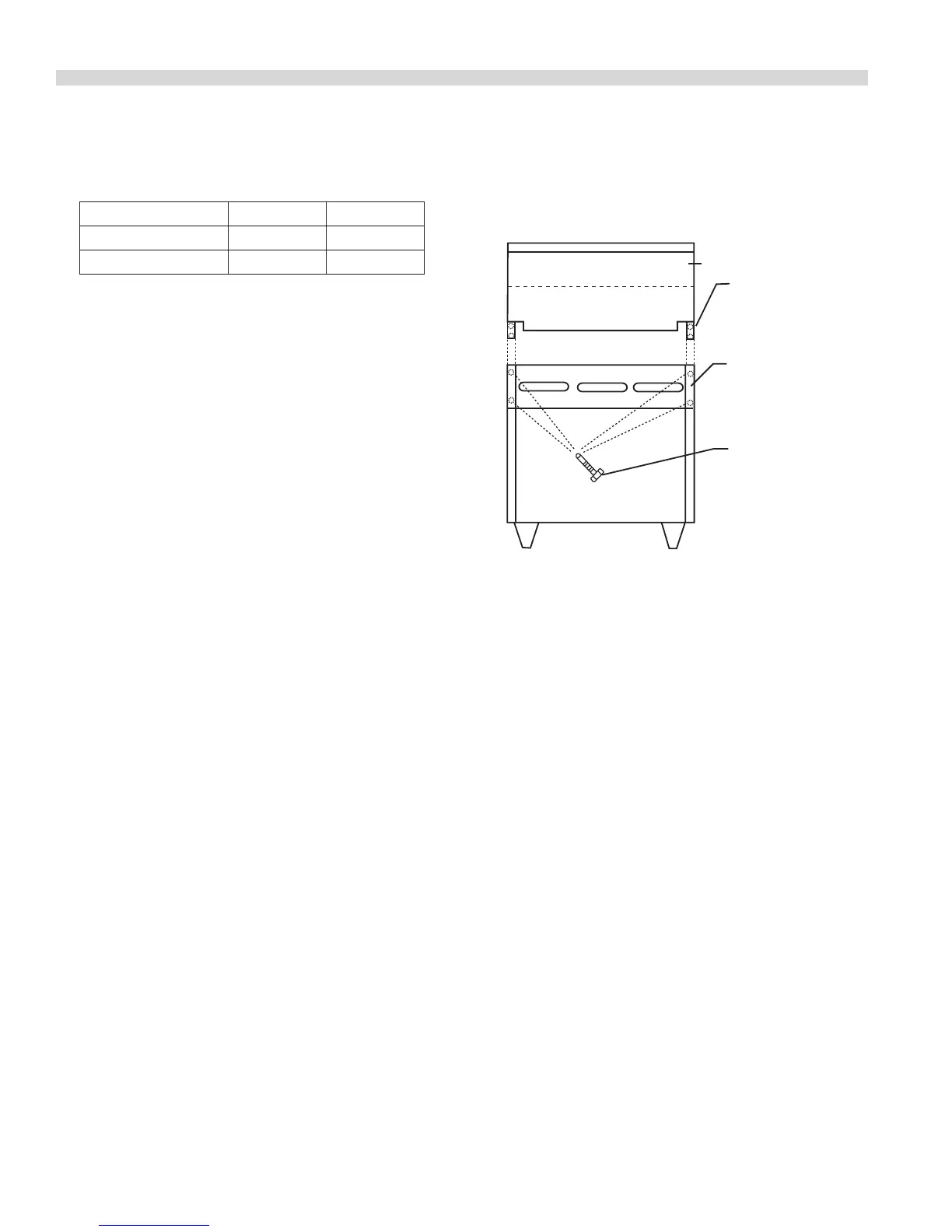
Installing The Backguard Or Shelf
1. Rear of range must be easily accessible.
2. Place the backguard, high shelf, salamander, or
cheesemelter on the rear of the range, slipping the
support brackets into the openings in the burner box
sides.
3. Securely fasten the support brackets to the burner box
sides with (4) #14 x 5/8 Hex washer head, type B tapping
screws. (Hardware package is supplied).
Upright
Burner Box
Side
#14 x 5/8"
Type "B"
Hex Head
Tapping Screw
4 Req'd
Ventilation Air
The following notes are intended to give general guidance.
For detailed recommendations, refer to the applicable
code(s) in the country of destination.
Proper ventilation is highly essential for optimum
performance. The ideal method of ventilating open-top
equipment is the use of a properly designed canopy that
should extend 152mm, beyond all sides of the appliance(s)
and 1981mm above the oor.
A strong exhaust will create a vacuum in the room. For an
exhaust vent to work properly, replacement air must enter
the room. The amount of air that enters must be equal to the
amount exhausted.
All gas burners and pilots need sucient air to operate. Large
objects should not be placed in front of the appliance(s) that
would obstruct the ow of air into the front.
Statutory Regulations
The installation of this appliance must be carried out by
a competent person and in accordance with the relevant
regulations, codes of practice and the related publications of
the country and destination.
 Loading...