SunFounder GalaxyRVR Kit for Arduino, Release 1.0
(continued from previous page)
Servo myServo; // create a servo object
void setup() {
myServo.attach(6); // attaches the servo on pin 6
}
void loop() {
myServo.write(90); // tell servo to go to 90 degrees
}
In this code, myServo is our Servo object, attach(6) tells the Arduino that our servo is connected to pin 6, and
write(90) tells the servo to move to 90 degrees.
Great job, explorers! You’ve just learned how to control a servo motor with Arduino. You can experiment with different
angles too!
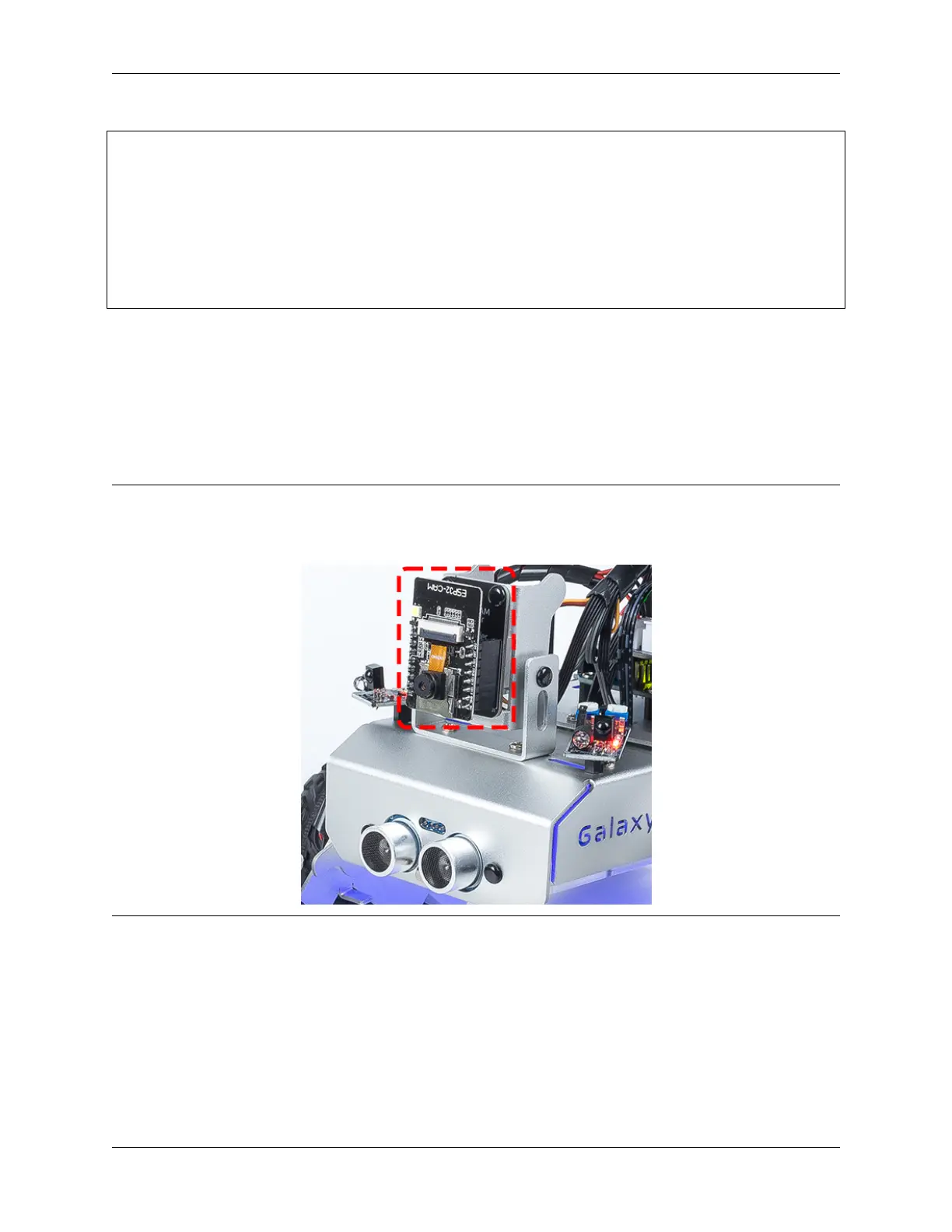
Step 4: Assemble the Visual System
You’re now ready to assemble the visual system of our Rover.
Note:
• When inserting the ESP32 CAM into the Camera Adapter, be aware of its orientation. It should align properly
with the ESP32 Adapter.
Step 5: Understanding the Limits of the Tilt Mechanism
Even though servo is designed to rotate between 0 and 180 degrees, you may notice that it stops responding beyond
a certain point (let’s say after 150 degrees). Have you ever wondered why this happens? Let’s explore this mystery
together in our next adventure!
Can you imagine a bird trying to bend its neck too much that it hits its own body and can’t move any further? Our
Rover’s tilt mechanism faces a similar situation. As the servo moves the mechanism downwards, it can bump into the
body of our Rover and can’t go beyond a certain angle.
If we try to force it to move beyond this point by writing an unreachable angle in our code, our little servo birdie can
3.10. Lesson 10: Exploring the Mars Rover Visual System - Servo and Tilt Mechanism 79