System Manual 7 Checking before Power-On and Power- Off
43
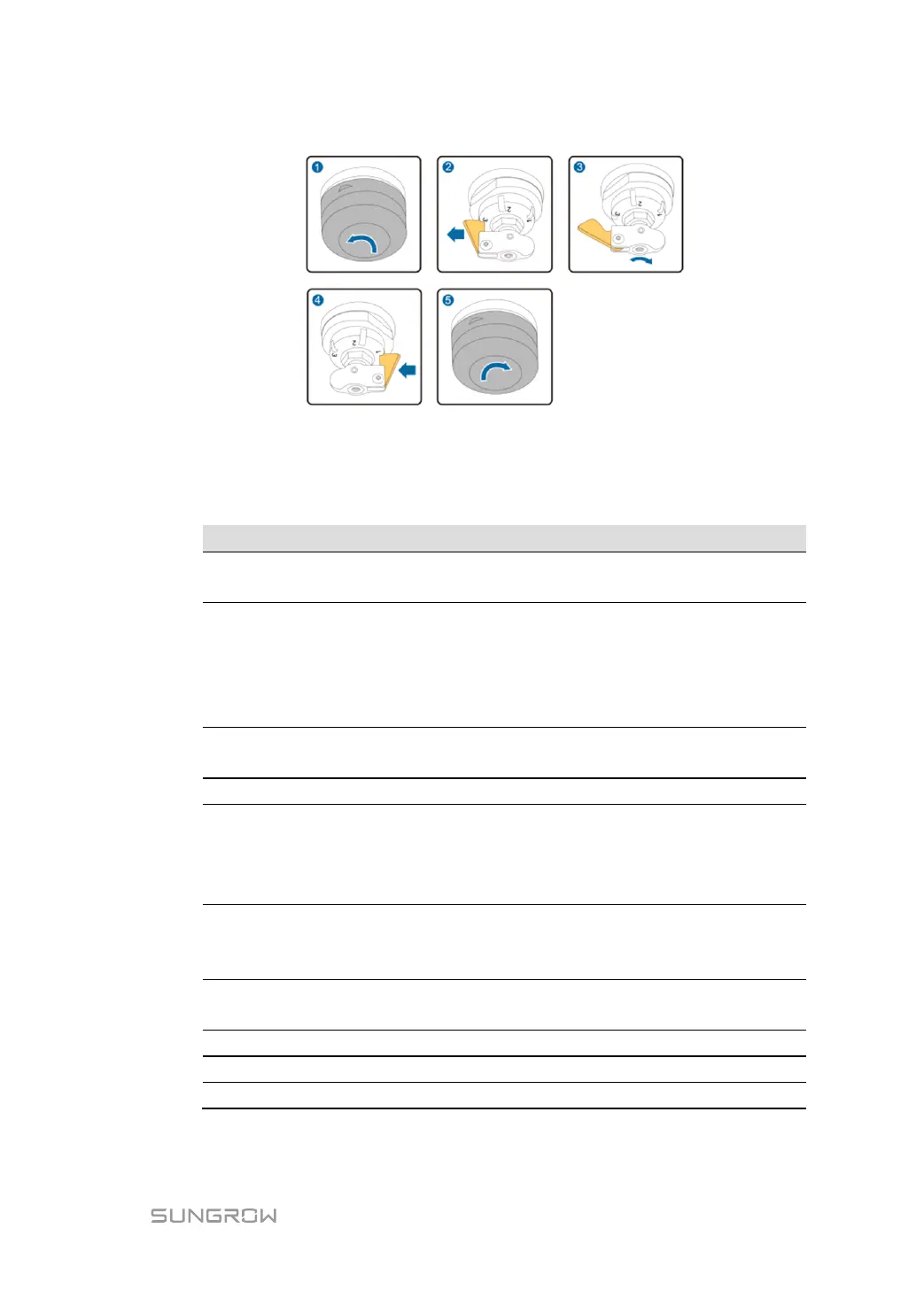
Fig. 7-2 Adjust the voltage ratio via the tap changer
7.4 LV Cabinet
The copper bar is not deformed, and no foreign matter is on the
copper bar.
Check and make sure the neutral point of the transformer is not grounded, the
input & output wiring to grounding resistance should be M Ω level; In the neutral
point grounding system, outgoing wiring copper bar resistance shall be M Ω level
and phase to phase resistance shall be M Ω level. (need to disconnect the
auxiliary circuit breaker, or phase to phase resistance is generally 0 Ω ).
Measure the fuse resistance. Resistances of three phases shall be small and the
value is similar.
Lightning protection status indicates green.
Pull the current terminal chip to the open position and measure the resistance at
both ends of the fracture. The value of three-phase resistance should be small and
close. After the measurement, restore the current terminal to the connected
position and tighten it. The standby current loop shall be shorted and grounded.
Apart the grounding yellow green wire of the secondary circuit and measure
secondary loop to the ground resistance and resistance should be M Ω level.
Recover the grounding wire and the resistance shall be 0 Ω.
The installation bolt of input cable has been tightened, and the cable is not loose
after pulling.
The cable inlet hole has been sealed.
Each component is intact.
Clear all foreign matter in the switchgear, such as tools and remaining materials.