19
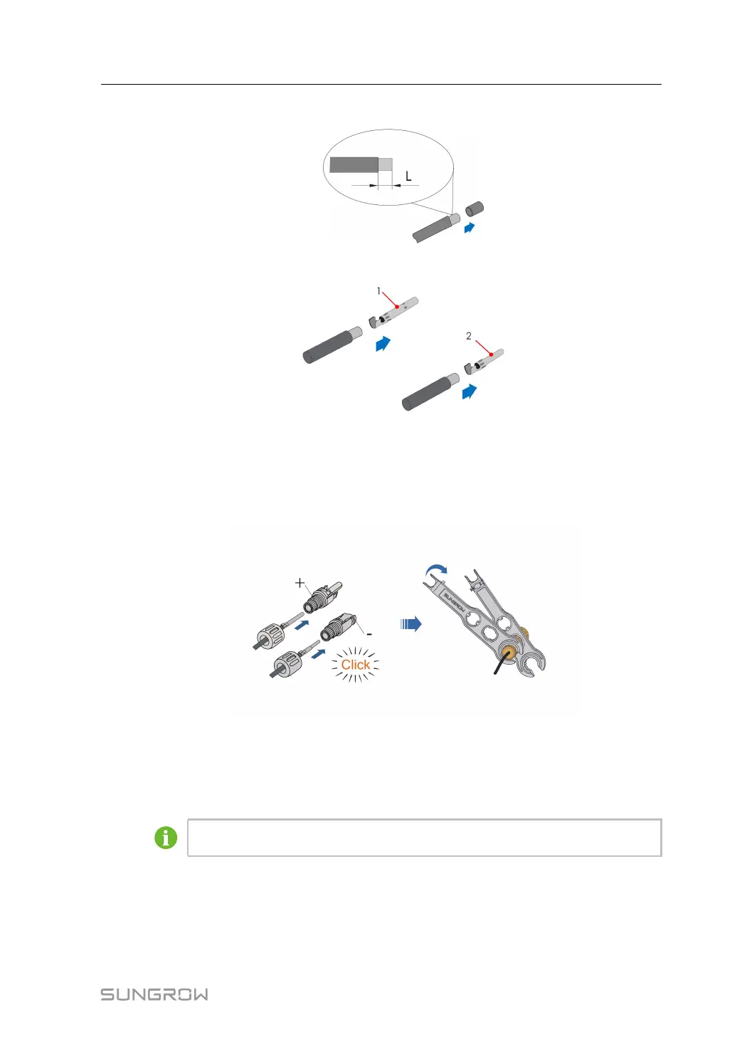
step 1 Strip the insulation from the cable by 7 mm - 8 mm.
step 2 Assemble the cable ends with the crimping pliers.
1: Positive crimp contact 2: Negative crimp contact
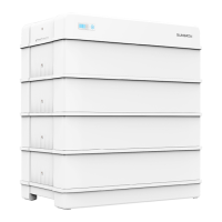
step 3 Lead the cable through cable gland, and insert the crimp contact into the insulator until it
snaps into place. Gently pull the cable backward to ensure firm connection. Tighten the ca-
ble gland and the insulator (torque 2.5 N•m to 3 N•m).
- - End
4.9 Assembling the Communication Connector
If the communication connector received is G2, please skip this step.
step 1 Unscrew the swivel nut from the connector.
User Manual 4 Mounting