73
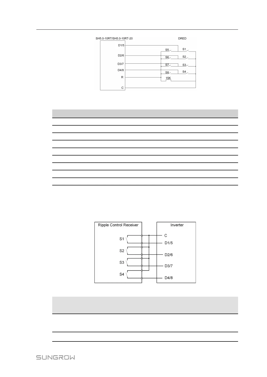
The switches that need to be closed in the state of DRM0 ~ DRM8 are shown in the table
below.
Demand Response Mode Operational Instruction Switch state
DRM0 OI0 Close S1 and S5
DRM1 OI1 Close S1
DRM2 OI2 Close S2
DRM3 OI3 Close S3
DRM4 OI4 Close S4
DRM5 OI5 Close S5
DRM6 OI6 Close S6
DRM7 OI7 Close S7
DRM8 OI8 Close S8
Ripple Control
In Germany, the grid company uses the Ripple Control Receiver to convert the grid dispatch-
ing signal and send it as a dry contact signal.
Wiring of the ripple control receiver dry contact cables is shown in the figure below:
table 6-6 Method of Asserting DI Mode
S-
1
S2 S3 S4 Switch Operation on
External RCR
Output power (in % of the Rated AC
output power)
0 0 0 0 None
100 % (configurable according to
need)
1 0 0 0 Close S1 100 %
User Manual 6 Electrical Connection
 Loading...