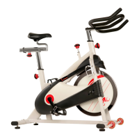
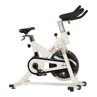
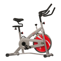
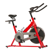
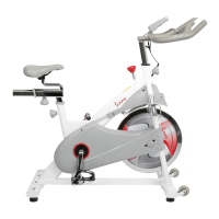
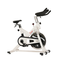
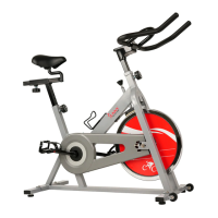
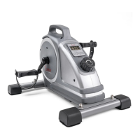
The device is a Chain Drive Premium Indoor Cycling Bike, model SF-B1509C, manufactured by Sunny Health & Fitness. It is designed for indoor use and is not intended for commercial or therapeutic purposes.
Function Description:
This indoor cycling bike provides a stationary exercise experience, simulating outdoor cycling. It features a chain drive system, adjustable resistance, and customizable fit for various users. The primary function is to offer a cardiovascular workout and improve fitness levels in a controlled indoor environment. The bike is equipped with pedals, a saddle, and handlebars, all of which are adjustable to ensure a comfortable and effective workout posture.
Important Technical Specifications:
- Model: SF-B1509C
- Drive System: Chain Drive
- Maximum Weight Capacity: 300 pounds
- Flywheel: 18Φ4603830Φ40*4 (No. 27)
- Pedals: YH-76X 9/16 (No. 41L/R)
- Crank: 9/16 (No. 11, No. 36L)
- Bearings: 6004-2RS (No. 42), 6001-2RS C & U (No. 29), 608ZZ Φ8 (No. 59)
- Frame: Main Frame (No. 1) with Front Stabilizer (No. 6) and Rear Stabilizer (No. 7)
- Adjustments: Saddle post (No. 2), Handlebar post (No. 4), Seat slider tube (No. 8), and Resistance (Tension Knob No. 47)
- Hardware: Various screws (M1025S6, M516Φ10, M612S5, etc.), nuts (M101.25H7.5S14, M8H5.5S14, M121H6S19, etc.), and washers (d10Φ202.0, d5Φ131, etc.)
- Tools for Assembly/Maintenance: Allen Wrench (S6, No. 79), Spanner (S14-15-17, No. 80), Open End Wrench (S13-15, No. 78)
- Dimensions (approximate, based on components): The flywheel diameter is approximately 460mm. The overall footprint is designed to require at least 2 feet of free space around it.
Usage Features:
- Adjustable Fit: The bike offers extensive adjustability to accommodate different user heights and body types.
- Saddle Height: The Saddle Post (No. 2) can be raised or lowered by loosening and pulling the Adjustment Knob (No. 16) outward.
- Saddle Fore/Aft Position: The Seat Slider Tube (No. 8) allows for forward and backward adjustment of the saddle by loosening and pulling the Adjustment Knob (No. 16) outward.
- Handlebar Height: The Handlebar Post (No. 4) can be adjusted up or down by loosening and pulling the Adjustment Knob (No. 16) outward.
- Resistance Adjustment: The resistance level is controlled by the Tension Knob (No. 47). Turning it clockwise increases resistance, while turning it counter-clockwise decreases it.
- Emergency Brake: Pushing down on the Tension Knob (No. 47) acts as an emergency brake, bringing the flywheel to an immediate stop.
- Pedal Straps: The pedals are equipped with toe clips and straps for securing the user's feet, ensuring stability and efficient power transfer during exercise. Users should place their feet as far forward as possible into the toe-clips and tighten the straps by pulling them upward and reinserting them into the hoop.
- Water Bottle Holder: A Water Bottle Holder (No. 21) is included for convenient hydration during workouts.
- Transportation Wheels: The front stabilizer is fitted with transportation wheels (No. 12) for easy relocation of the bike. To move, grasp the handlebar, place one foot on the front stabilizer, and tilt the bike until the wheels engage the ground.
- Foot Levelers: Adjustable Foot Levelers (No. 15) are located beneath the front and rear stabilizers to ensure the bike remains stable and level on uneven surfaces. These are adjusted by loosening Nut (No. 48) with a spanner, rotating the foot leveler, and then re-tightening the nut.
- Safety Warning: The bike is not designed for reverse pedaling. Users are warned that failure to comply may result in permanent damage.
Maintenance Features:
- Regular Inspection: The safety of the equipment depends on regular examination for damage, wear, and tear. All nuts and bolts should be securely tightened before each use.
- Lubrication: All moving parts are recommended to be lubricated on a monthly basis.
- Troubleshooting: If any defective components are found during assembly or inspection, or if unusual noises occur during exercise, users should stop using the equipment immediately and not resume use until the problem is rectified.
- Chain Adjustments: The manual provides detailed instructions for adjusting the chain, which involves removing various covers (End Cap No. 70, Outer Chain Cover No. 68, Front Cover No. 69, Left Stay Cover No. 58) and adjusting nuts (No. 32, No. 34, No. 66) on the flywheel (No. 27) using specific tools (Cylinder Allen Wrenches S19, S18, S13, and Spanner No. 80). The process ensures the chain (No. 38) is secured and the flywheel is centered.
- Storage: The product should be stored in cool, dry conditions to prevent corrosion and other related problems. Extreme cold, hot, or damp areas should be avoided.
- Cleaning: Wear suitable clothing and avoid loose clothing that may become entangled in the equipment. Keep children and pets away from the equipment.