28
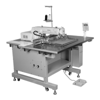
C. Setting the trimming shaft in place
ⓐ Unfasten the trimming drive link screw and the trimming shaft collar screw.
ⓑ Make the trimming shaft step accord with part of the arm.
ⓒ Tighten the screws.
[ Fig. 51 ]
Thread Trimmer Shaft
Thread Trimmer Cam
Screw
Thread Trimming
Driving Link
Collar for
Thread Trimmer Shaft
D. Setting the Link Stopper in Place
ⓐ Unfasten the trimming drive link stopper
screw while trimming is not operated and
have the trimming drive link and the
trimming drive link stopper notch 0.3mm
apart from each other.
ⓑ Tighten the screw.
[ Fig. 52 ]
→
→
0.3mm
Thread
Trimmer
Driving
Link
Screw
Thread Trimmer Driving
Link Stopper
→
→
0.3mm
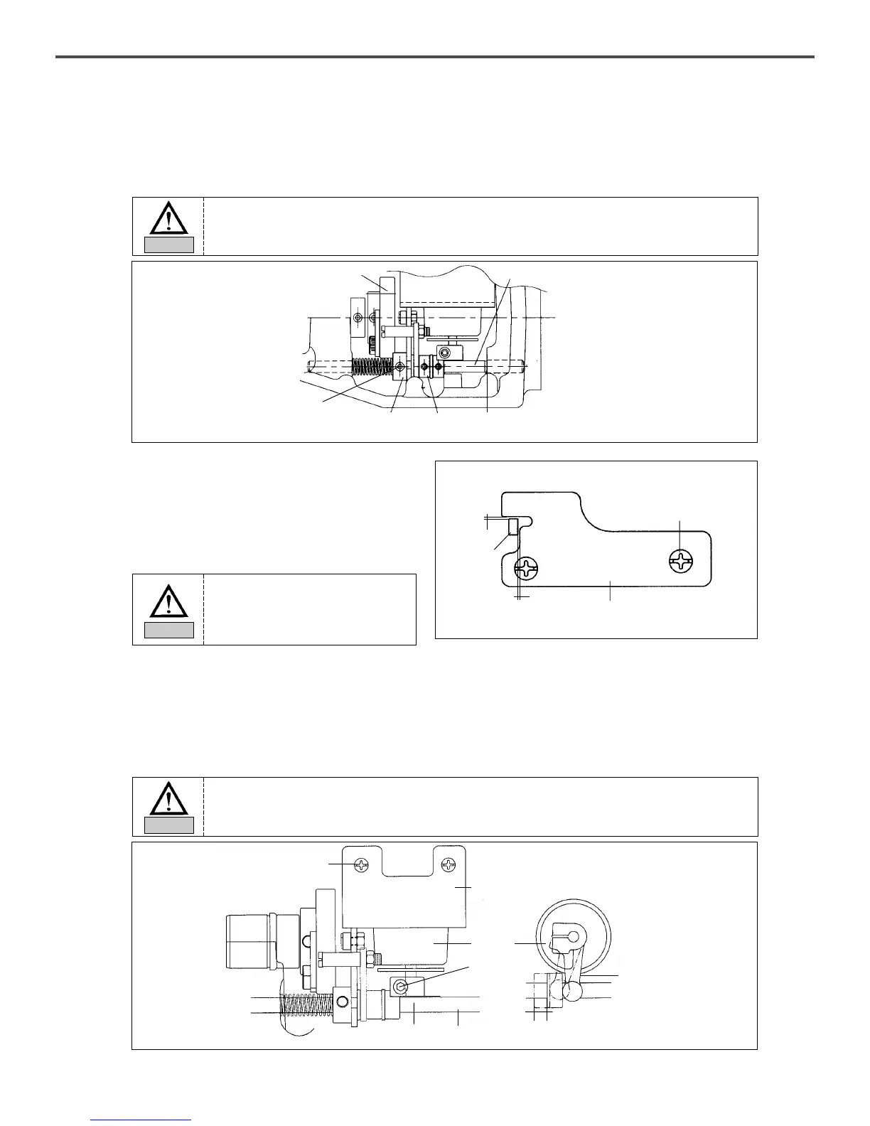
E. Setting the Thread Trimming Solenoid in Place
ⓐ After unfastening the thread trimming solenoid bracket screw, have the trimming shaft and the thread
trimming solenoid rotary link 0.5mm apart from each other and tighten the screw back on.
ⓑ Unfasten the thread trimming solenoid rotary link screw and drive the thread trimming solenoid rotary
link manually to move the trimming shaft collar 6.8mm in the direction of the arrow. Then, tighten the
screw back on.
ⓒ Check if the trimming shaft collar returns to its place when the thread trimming solenoid rotary
link returns.
[ Fig. 53 ]
→
→
0.5mm
Solenoid
Thread
Trimming
Rotation Link
Thread Trimmer Solenoid Bracket
Screw
Screw
Thread Trimmer Shaft
Thread Trimming Rotation Link
6.8mm
→
→
If the position is not adjusted appropriately, trimming may not be operated correctly or
the machine may be lock.
Caution
If the position is not set right, the trimming return or the thread delay may be delayed to bring poor
sewing quality.
Caution
If the link stopper is not set in the
right position, trimming may not be
operated correctly and the machine
may be lock.
Caution
 Loading...