31
INSTALLATION and OPERATION MANUAL
INSTALLATION and OPERATION MANUAL
INSTALLATION and OPERATION MANUAL
INSTALLATION and OPERATION MANUAL
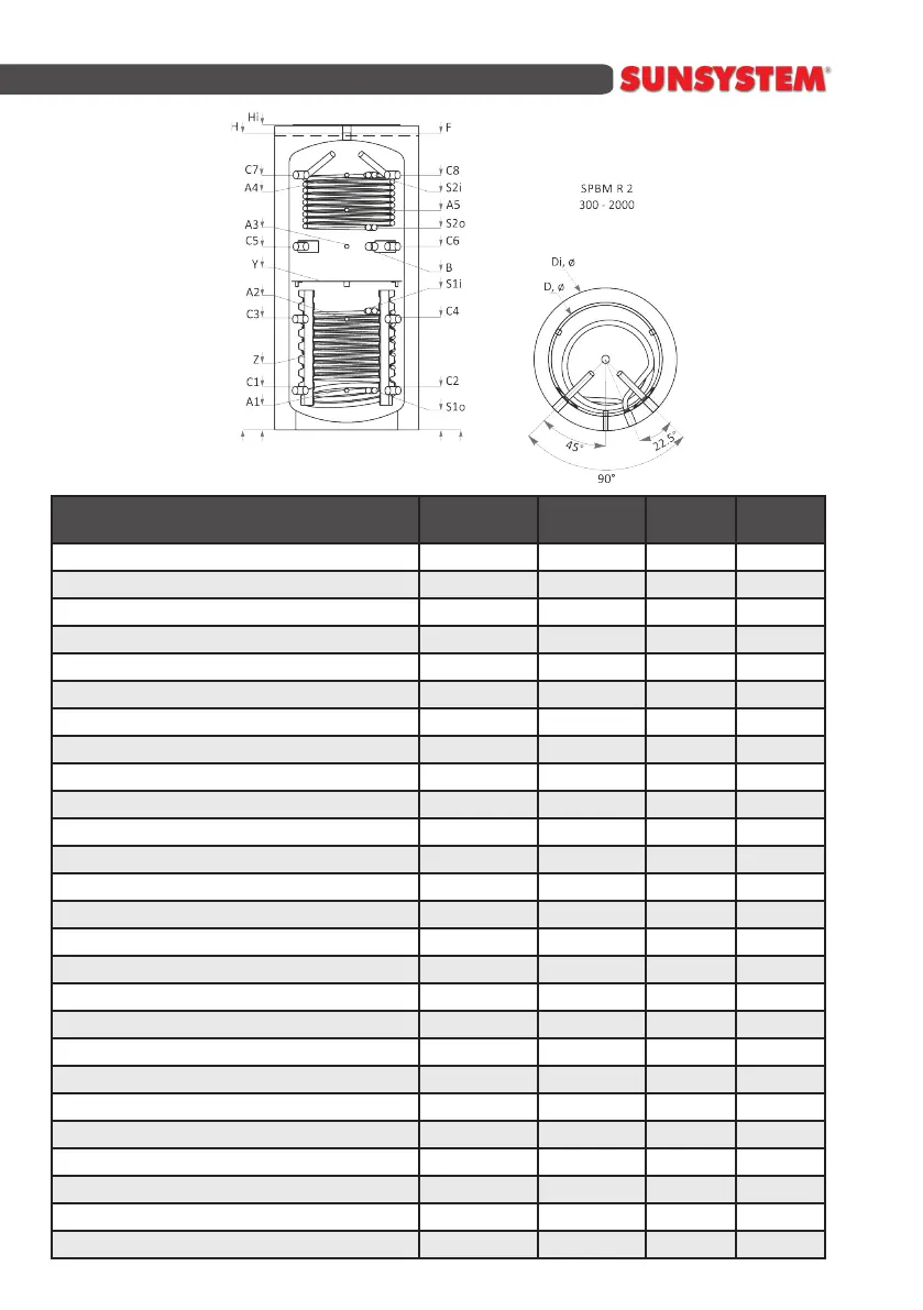
SPBM R2
1000
SPBM R2
1500
SPBM R2
2000
Capacity L 1000 1500 2000
Heightwithoutinsulaon/withinsulaon H,Hi,mm 2039/2089 2140/2290 2131/2181
Minimalvercalclearance mm 2073 2192 2220
Diameterwithoutinsulaon/withinsulaon D,mm Ø790/990 Ø1000/1200 Ø1200/1400
Operangpressure/Max.buertemperature bar/
0
C 3/95 3/95 3/95
Operangpressure/Max.coiltemperature bar/
0
C 16/110 16/110 16/110
Recommendedboilersize,connectedtobuertank kW 18-33 27-50 36-67
Weightwithoutinsulaon/withinsulaon kg,kgi 191/209 287/310 360/387
SleeveforElectricheangelement В,mm,Rp1
1/2
” 1260 1260 1308
Heatcarrier С1,mm,Rp1
1/2
” 290 339 388
Heatcarrier С2,mm,Rp1
1/2
” 290 339 388
Heatcarrier С3,mm,Rp1
1/2
” 775 833 848
Heatcarrier С4,mm,Rp1
1/2
” 775 833 848
Heatcarrier С5,mm,Rp1
1/2
” 1260 1327 1308
Heatcarrier С6,mm,Rp1
1/2
” 1260 1327 1308
Heatcarrier С7,mm,Rp1
1/2
” 1750 1821 1768
Heatcarrier С8,mm,Rp1
1/2
” 1750 1821 1768
Sensorsleeve А1,mm,Rp1/2” 290 339 388
Sensorsleeve А2,mm,Rp1/2” 775 833 848
Sensorsleeve А3,mm,Rp1/2” 1260 1327 1308
Sensorsleeve А4,mm,Rp1/2” 1750 1821 1768
Airventsleeve F,mm,Rp1
1/2
” 2039 2140 2131
Capacitylower/uppercoilS1/S2 S1/S2L 15.2/10.5 20.65/11.85 30/12.4
HeatexchangesurfaceS1/S2 S1/S2m
2
2.48/1.71 3.4/1.93 4.9/2.0
Inlet/OutletLowercoiS1 S1i/S1o,mm,Rp1” 830/290 939/339 1158/388
Inlet/OutletUppercoilS2 S2i/S2o,mm,Rp1” 1750/1390 1821/1506 1768/1503