Do you have a question about the SunTech ST3300 and is the answer not in the manual?
Describes the device's three operation modes: driving, parking, and emergency.
Details AVL reports, alerts, and report types, including storage and priority.
Device can process two steps of power-down, Sleep and Deep Sleep.
LED indicates WCDMA and GPS states. It's helpful to check error cause.
Device has 2 output lines, 3 input lines and ignition line.
Remote firmware updates via WCDMA for error correction or new services.
Checks vehicle movement off boundary or unauthorized driving without ignition.
Monitors vehicle speed and sends over-speed alerts to the server.
Alerts when the GPS antenna is disconnected.
Defines the structure and fields for command messages sent from server to device.
Defines the structure and fields for report messages sent from device to server.
Sets network parameters like WCDMA, APN, server IP, and PIN number.
Interval for sending status report in parking mode. Range: 0~86400.
Interval for sending status report in driving mode. Range: 0~60000.
Interval for sending status report in emergency mode. Range: 0~9999.
Number of attempts for emergency report until device gets acknowledge.
Distance interval for sending status report. Range: 0~60000.
Interval for sending keep alive string.
Interval for sending status report in parking mode via SMS.
Interval for sending status report in driving mode via SMS.
Report No in one SMS message.
Report STT message if it's greater than ANGLE_RPT.
Set the type of reporting (FIFO or LIFO).
Delay for entering idle mode after ignition goes to off.
Delay for entering active mode after ignition goes to on.
Defines input types: Falling Edge, Rising Edge, Panic Button, Call, Anti-Theft.
Input1 chattering time. Range: 0~9999.
Defines output types: GPIO, Immobilizer, Pulse, LED, Buzzer.
Sets the active state for output 1 (Open or GND).
Pulse number when output type is set to pulse. Range: 0~9999.
Active time of pulse1. Range: 0~9999.
Inactive time of pulse1. Range: 0~9999.
Baud rate setting for RS232 communication.
Ignition using state: Not use, Use Line, Virtual Ignition.
Delay for entering idle mode after ignition goes to off.
Delay for entering active mode after ignition goes to on.
Defines input types, including Anti-Theft button and Immobilizer disable.
Input1 chattering time setting. Range: 0~9999.
Defines output types.
Sets active state for output 1.
Lock of receiving commands by SMS (Disable/Enable).
Phone numbers for SMS commands.
Lock of incoming calls (Disable/Enable).
Phone numbers for accepted calls.
Phone numbers for outgoing calls from device.
Enable/disable parking lock feature and its behavior.
Sets the over-speed limit and alert behavior.
Configuration for power saving modes (sleep, deep sleep).
Sets the connection type with the server (KEEP_CON, KEEP_DISCON, KEEP_NOP).
Enable/disable ZIP compression for data transmission.
Enable/disable group sending of stored data packets.
Enable/disable Main Power disconnection check.
Enable/disable GPS Antenna connection error check.
Enable/disable Backup Battery error check.
Configures motion sensor parameters (Motion, Collision, Shock detection).
Enable/disable support for call with headset.
Enable/disable Geo-fence feature.
Enable/disable data logging via RS232.
Parameter for jamming detection, assist function.
Parameter for jamming detection, assist function.
Server Protocol Type (TCP/UDP).
Backup Server Protocol Type (TCP/UDP).
ACK from Server when UDP is used (No use, ACK for reports, ACK for emergency).
Device's port for receiving commands from UDP server.
Voltage value to stop backup battery charging in 12V vehicle.
Voltage value to check vehicle battery status.
Voltage value to protect vehicle battery.
Virtual ignition setting for driving state detection.
Virtual ignition setting for parking state detection.
Delay for entering shock detection mode after ignition off.
Detection level for motion violation.
Detection level for shock violation.
Gravity setting for collision report.
Threshold value for Motion Virtual Ignition On.
Delay time for Motion Virtual Ignition On.
Percent for Motion Virtual Ignition On.
Threshold value for Motion Virtual Ignition Off.
Delay time for Motion Virtual Ignition Off.
Percent for Motion virtual Ignition Off.
Control command content field.
Location poll and status report request.
Resets all parameters to factory values and reboots the device.
Resets parameters and reports current device status.
Acknowledgement of emergency report to stop further reports.
Activates Output1 for specific functions like immobilization or pulsing.
Deactivates Output1.
Requests the unique SIM ID of the inserted SIM card.
Requests the ICCID of the inserted SIM card.
Requests the device's software version information.
Erases all saved reports and disables outputs for initialization.
Resets the traveled distance counter to zero.
Resets the message sequence number to zero.
Reboots the device.
Requests the local IP address assigned to the SIM card.
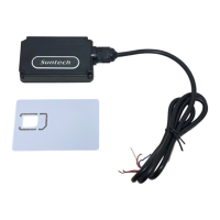
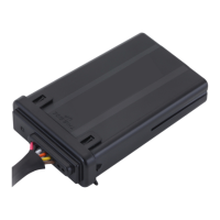
Instructions on how to insert the SIM card into the device.
Information about using the backup battery when main power is cut off.
Guidelines for physically installing the device in the vehicle.
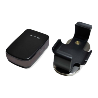
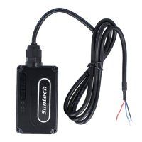
Visual guide for assembling device components.
Description of the red wire's function (Power input).
Description of the black wire's function (Ground connection).
Description of the blue wire's function (Ignition signal).
Description of the white wire (Input1) for the panic button.
Description of the yellow wire (Input2) for event reporting.
Description of the green wire (Input3), similar to Input2.
Description of the orange wire (Output1) function.
Description of the brown wire (Output2) function.
Visual representation of the immobilizer's progressive blocking behavior.
Describes the operation when an output is dedicated to PULSE.
Time required for GPS connection.
Explains WCDMA status indicated by the blue LED and possible causes.
Explains GPS status indicated by the red LED and possible causes.
Statement regarding FCC RF radiation exposure limits and operating conditions.
Information on FCC compliance, subject to two conditions.
Cautionary notes on USB connect usage and product fixing.
| Channels | 72 |
|---|---|
| Update Rate | Up to 10 Hz |
| Accuracy | 2.5m CEP |
| Storage Temperature | -40°C to +85°C |
| Humidity | 5% to 95% non-condensing |
| GNSS | GPS, GLONASS, BeiDou, Galileo |
| Acquisition Time (Hot Start) | 1s |
| Current Consumption | 30mA |
| Interface | UART |