20 21
Figure 4-17
Figure 4-18
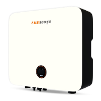
3) Put the AC cable through the cable gland and use a socket spanner to lock all cables to the
correspondingly AC connector and pull back them with some power to make sure they’re well
connected. As shown in Figure 4-17:
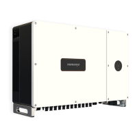
4) Insert the at cable of the display back to its place and put back the right roof cover and
lock with its original screws. As shown in Figure 4-18:
Figure 4-16
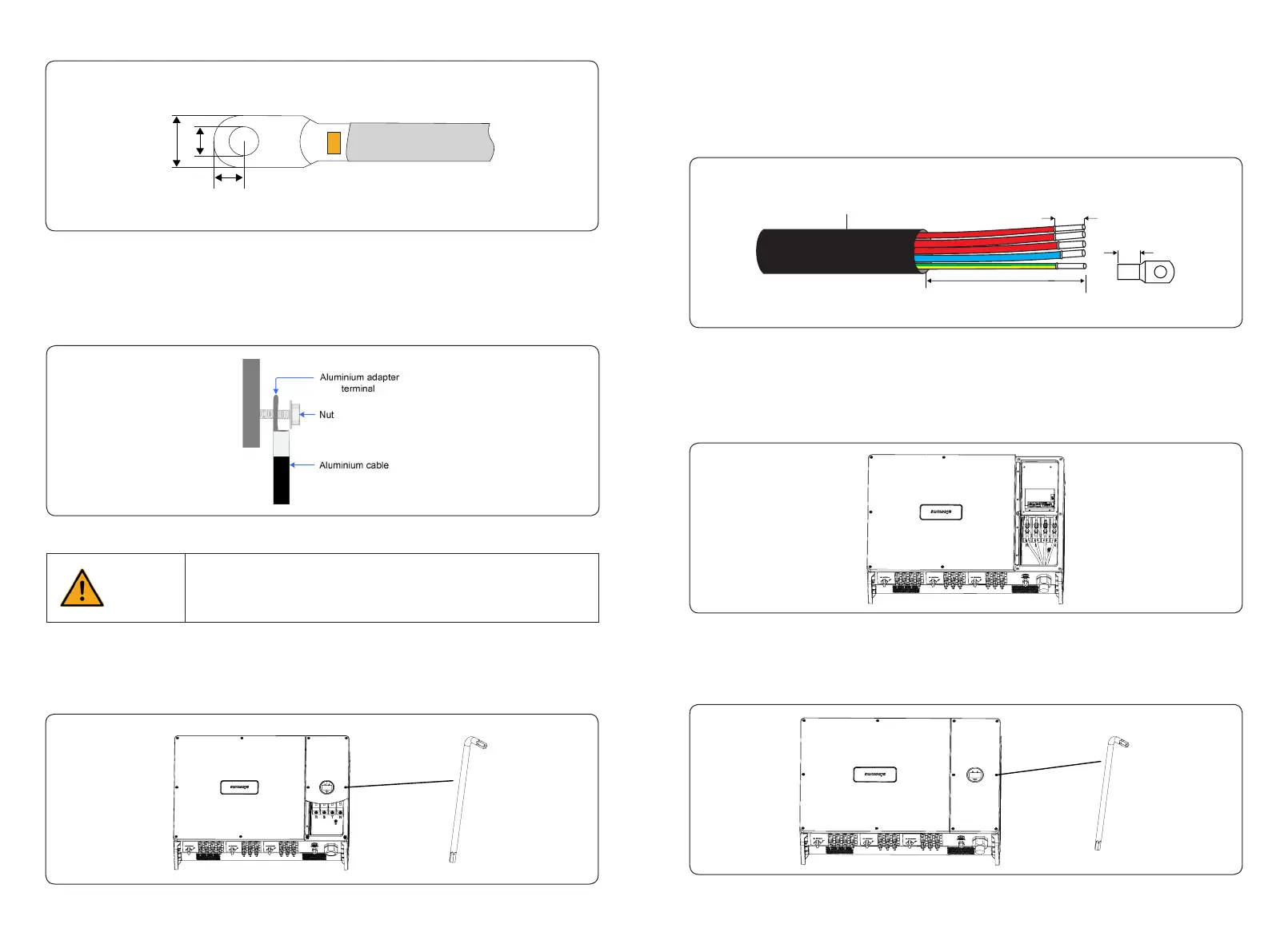
2) Put the cable through the cable gland, and strip o the outer insulation sheath ≤ 160mm,
according to the size of OT/DT terminals to peel o a proper length of the 3L /PE / N wires, then
insert the conductor core into the OT/DT terminals and press with a hydraulic clamp. As shown
in Figure 4-16:
≤ 160mm
Strip Length:L
L
Outside Diameter:30~45mm
L1
L2
L3
PE
N
4.3.2.1 AC connector connection steps
1) Take out the ring spanner from the accessory box and remove the right roof cover after
unscrewed the screws on it, as shown in Figure 4-15:
Figure 4-15
3) Aluminium cable requirements
If an aluminium cable is selected, use a copper to aluminium adapter terminal to avoid direct
contact between the copper bar and the aluminium cable.
Direct contact between the copper bar and aluminium wire may arise
electrochemical corrosion, thus aect the reliability of the electrical connection.
If an aluminium wire is used, please use a copper-aluminium wire terminal to
avoid direct contact between the copper bar and aluminium wire.
Caution
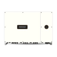
Figure 4-14
a b
c
Figure 4-13 OT / DT terminals of phase wire