26 27
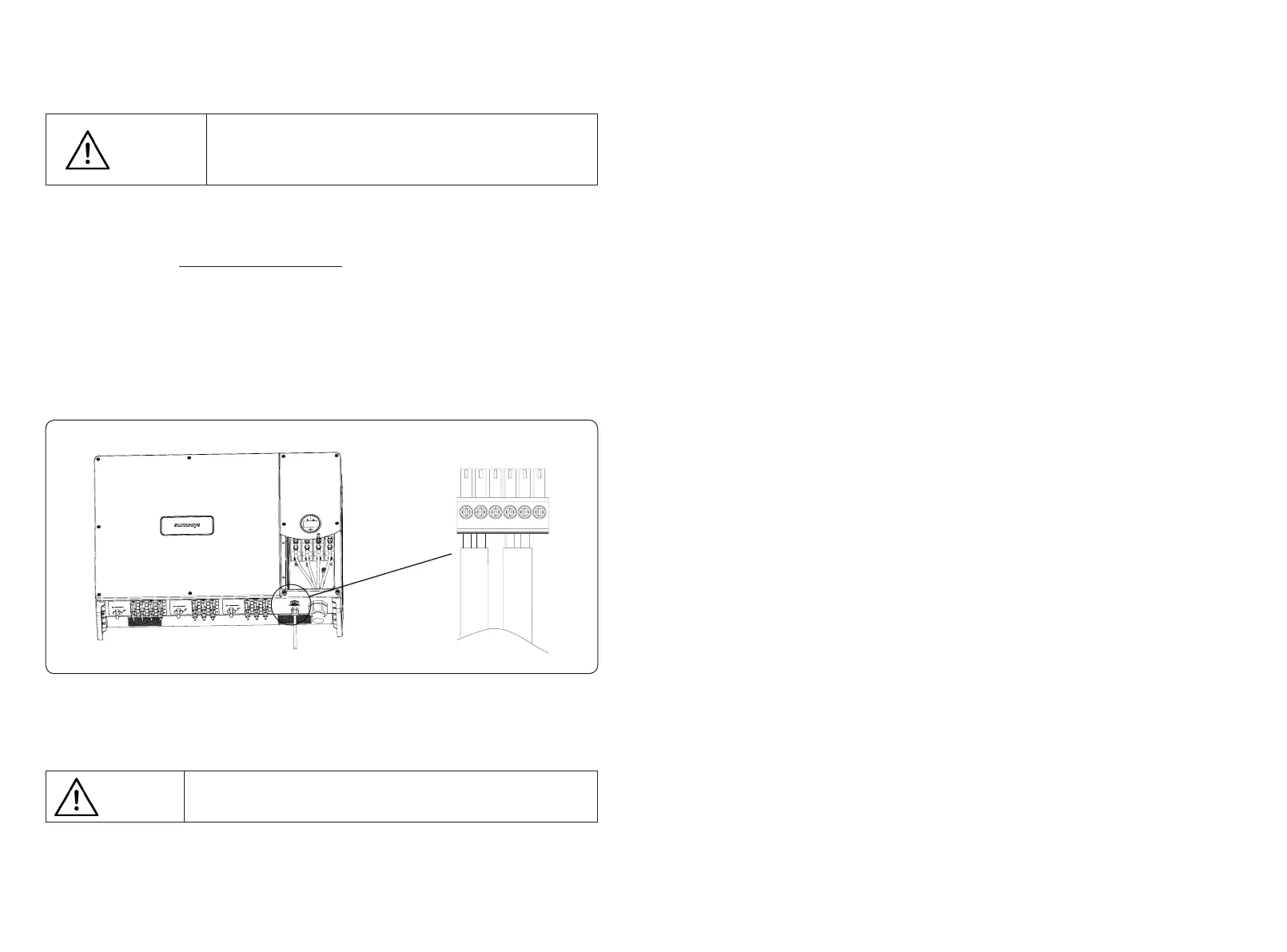
Figure 4-25 RS485 communication port schematic diagram
1
4
2 53 6
RS485 cable requirements: Shielded twisted-pair cable or shielded twisted
Ethernet cable.
Attention
5. Start and Stop
5.1 Inverter start-up
When starting the inverter, follow these steps:
1) Turn on the AC breaker rst.
2) Turn on the three DC switches in the bottom. If the PV string voltage higher than the inverter
start-up voltage, the inverter will start.
3) When both AC and DC power supply are normal, the inverter is ready to start. The inverter
will initiate from checking its internal parameters and grid parameters, if it’s within the range,
the green light on the left side of the screen begins to ash, and the “Waiting” message will be
displayed on the OLED display.
4) After self-checking completed, the inverter will start generating electricity, the green light
will remain on, and the OLED display will display real-time power information.
5.2 Inverter shutdown
When turning o the inverter, please follow the steps below:
1) Turn o the AC breaker rst.
2) Wait 30 seconds and then turn the three DC switches to the “OFF” position. At this time,
there is remaining power in the inverter capacitor. Wait for 5 minutes until the inverter is
completely de-energized before operating.
3) Disconnect the AC and DC cables.
4.5.3 Anti-reverse or power limit solution
Anti-reverse or power limit solution, wiring instructions and conguration, please contact
Sunways after-sales at service@sunways-tech.com.
4.5.4 RS485/DRED connection steps:
1) Remove the right roof cover of the inverter with a cross screwdriver.
2) Put the cables which you need through the cable gland, as shown in Figure 4-25:
3) Insert the cable to the port in the 6pin connector and fasten with a screwdriver.
4) Insert the 6pin connector into the 6pin connecter inside the inverter, and screw the roof
cover back with a cross screwdriver.
The maximum distance between the inverter at the end of the daisy chain and the data logger
should be within 1000M.
Suggest using the RS485 communication cable with a cross-sectional area
of 0.75-1.5mm² and an outer diameter of 5mm-10mm.
RS485 cable requirements: Shielded twisted-pair cable or shielded twisted
Ethernet cable.
Attention
Suggest to use the communication cable with the cross-sectional area of 0.75-1.5mm² and
outer diameter of 5mm-10mm.