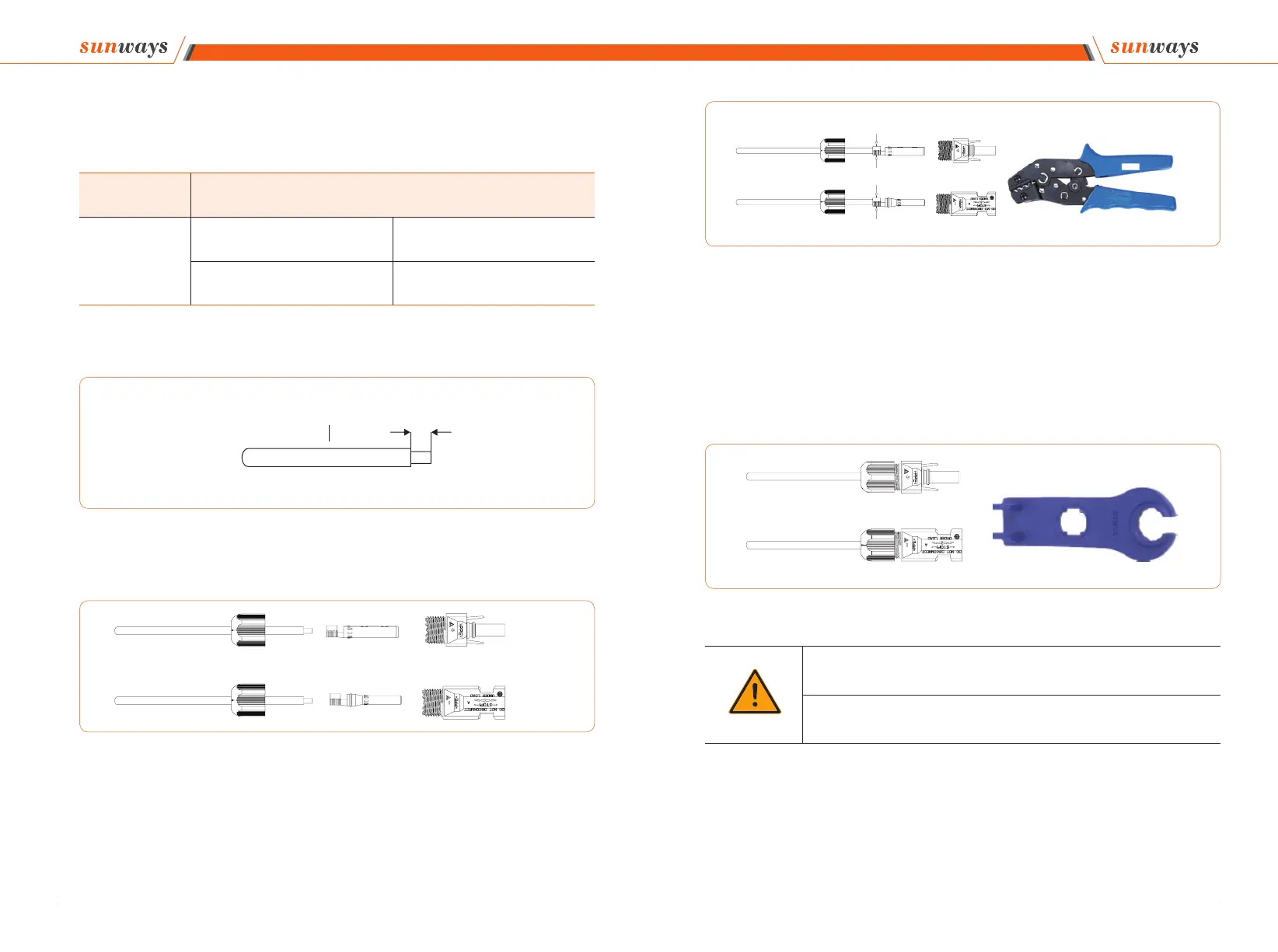
2. DC connector assembly procedure
Cable type Traverse area (mm²)
General photovoltaic
cable
Range (mm
2
) Recommended value (mm
2
)
2.5-4.0 4.0
Figure 4-9
Wire Traverse area 2.5-4mm
2
7mm
Figure 4-10
3.Insert the positive and negative connectors into the inverter DC input terminals re-
spectively, a click sound should be heard if the terminals are well connected, as shown
in Figure 4-13:
Figure 4-11
Figure 4-12
Warning
① Before assembling the DC connector, make sure that the cable polarity is correct.
② Use a multimeter to measure the voltage of the DC input string, verify the polarity of
the DC input cable, and ensure that each string voltage is within 1000V.
4 Installation 4 Installation
+
-
Crimping Plier
Open-end Wrench